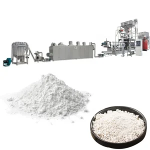
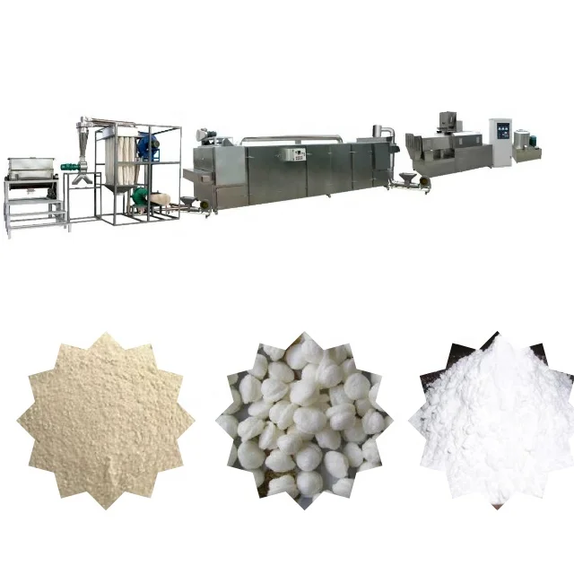
Screw Geometry Dictates Modification — Every MT series extruder barrel is sectioned so temperature and shear can be tuned independently to the starch source you actually run.
Technical Specifications
| Parameter | Value |
|---|---|
| Product Type | Modified Starch Twin Screw Extrusion Processing Line |
| Model Options | MT65 / MT70 / MT85 |
| Screw Configuration | Twin-screw, configurable element arrangement |
| Line Sequence | Mixing → Extrusion → Drying → Grinding → Blending → Packing |
| Control Architecture | PLC and MCC integrated across stations |
| Raw Material Scope | Corn, potato, cassava, maize, tapioca starch |
| MT65 Line Power | 60 kW |
| MT65 Line Dimensions | 24000 × 1200 × 2200 mm |
| MT65 Output Capacity | 100–150 kg/h (basis not stated in source — confirm raw material type / moisture content / starch source) |
| MT70 Line Power | 80 kW |
| MT70 Line Dimensions | 26000 × 1500 × 2200 mm |
| MT70 Output Capacity | 200–250 kg/h (basis not stated in source — confirm raw material type / moisture content / starch source) |
| MT85 Line Power | 145 kW |
| MT85 Line Dimensions | 29000 × 3500 × 4300 mm |
| MT85 Output Capacity | 300–500 kg/h (basis not stated in source — confirm raw material type / moisture content / starch source) |
| Compliance | CE, ISO |
Application Suitability
| Application | Material or Output |
|---|---|
| Modified starch for food thickeners and stabilizers | Corn starch, potato starch |
| Pre-gelatinized starch for instant food products | Maize starch, tapioca starch |
| Industrial binder starch for paper and textile sizing | Cassava starch, corn starch |
| Oil drilling fluid starch modification | Native starches requiring thermal-chemical treatment |
| Nutritional powder base starch processing | Blended starch sources with additive incorporation |
Why Your Starch Source Invalidates a Generic Screw Build
A screw combination designed for corn starch will underperform on cassava or potato starch because gelatinization temperature and shear tolerance differ fundamentally.
When buyers request a modified starch processing line full equipment range, the conversation often stalls at capacity numbers while the actual variable — screw element arrangement and barrel temperature profile — remains unspecified. I have watched lines ship with a default screw build that produced acceptable viscosity on corn starch during factory trials, only for the buyer to switch to a local cassava supply and find the gelatinization incomplete and the final product failing specification. The dryer and grinder downstream then face a feed material that is either too wet or too degraded, and the entire line stalls at a fraction of its intended throughput [NEED_CITE: starch gelatinization temperature variation across botanical sources].
How Barrel Sections and Screw Elements Define the Reaction Zone
The twin-screw extruder in a modified starch processing line full equipment range operates as a continuous reactor where moisture, temperature, and mechanical shear drive the physical and chemical modification of the starch granule. Each barrel section can be heated or cooled independently, and the screw elements — conveying, kneading, reverse — are arranged in a sequence that determines residence time and shear intensity at each stage. A potato starch, which gelatinizes at a lower temperature than corn starch, requires a gentler thermal profile and shorter high-shear zone to avoid molecular degradation. This configurable geometry is what separates a line that runs your specific material from one that merely runs starch in the abstract.
Matching Downstream Stations to the Extruder’s Actual Output
A modified starch processing line full equipment range is only as productive as its most constrained station. The dryer must handle the exact moisture content exiting the extruder die, which varies depending on the starch source and the degree of modification targeted. The grinder must reduce the dried extrudate to a particle size distribution that meets the buyer’s specification, and its throughput must align with the extruder’s actual running output — not a catalog figure derived from a different material. When these stations are sourced from separate vendors without a unified throughput calculation, mismatches emerge during commissioning and the line never reaches its design capacity [NEED_CITE: industrial drying load calculation for extruded starch products].
Reading the Power and Dimension Data Correctly
The MT65, MT70, and MT85 designations represent three tiers of installed power — 60 kW, 80 kW, and 145 kW respectively — which correlate to the mechanical energy available for shear-induced modification inside the barrel. Higher power enables processing of more viscous starch slurries or the incorporation of reactive additives that increase resistance inside the extrusion chamber. The line dimensions scale accordingly, with the MT85 occupying 29000 × 3500 × 4300 mm, a footprint that dictates workshop layout and utility routing. Mixer output and extruder main motor ratings must be cross-referenced against your batch cycle time to confirm that material is always available at the extruder feed hopper without interruption or excessive hold time that allows the slurry to settle.
The Cost of Skipping the Trial Run
Lines commissioned without a prior trial on the buyer’s actual raw material frequently require weeks of on-site adjustment, during which the screw configuration, barrel temperature, and moisture addition rate are all modified iteratively. This delay consumes raw material, occupies technical staff, and postpones revenue production. In some cases, the default die design produces an extrudate shape that dries unevenly, forcing a reduction in dryer belt speed and cutting effective output across the entire modified starch processing line full equipment range [NEED_CITE: importance of factory trial runs for extrusion-based starch modification].
Why Sourcing Every Station from One Manufacturer Matters
The complete line from mixing through packing is engineered under a single supplier, meaning throughput at each station is calculated relative to the others rather than assumed from catalog ratings. Screw configuration and die design are specified against your stated starch source and target modification, not copied from a generic build. The PLC and MCC control system integrates every station, so process parameters are managed from a single interface rather than through disconnected controls on equipment from multiple vendors. An in-house testing workshop allows trial runs on your actual material before shipment, reducing the risk of commissioning delays. Documentation — including line layout, capacity calculations, and screw configuration records — accompanies every delivery so your technical team can replicate proven settings on subsequent production runs.
Documentation & Verification
- Line layout and capacity calculation matching every station to your starch source and target output.
- Screw and die configuration record documenting element arrangement selected for your material.
- Trial run report on your actual raw starch conducted in the testing workshop before dispatch.
- Electrical schematic with voltage, frequency, and control language confirmed for your facility.
- CE declaration of conformity and ISO certificate applicable to the complete processing line.
Installation, Commissioning & Support
- Foundation plan provided based on MT85 dimensions and weight distribution for stable extruder mounting.
- Electrical supply specification detailing total line power requirement and dedicated circuit allocation for the extruder main motor.
- Assembly sequence documented for all stations from mixer through packing, with alignment tolerances specified.
- Commissioning protocol covering PLC parameter upload, barrel temperature calibration, and screw speed ramp-up.
- Operator training on screw element replacement, die cleaning, and MCC fault diagnosis for the integrated control system.
- Wear parts list identifying screws, dies, and barrel liners with recommended first-year spare stock quantities.
What We Need to Configure Your Line
To prepare a line layout and quotation, provide the specific starch source you will process — corn, cassava, potato, or a blend — along with the target modification type and any additive incorporation requirements. State your intended daily output and the number of operating shifts so capacity can be sized correctly. Confirm the voltage and frequency at your facility, and indicate the preferred language for the PLC and MCC interface. If you have existing upstream or downstream equipment that must integrate with the new line, share the specifications so throughput matching accounts for the full production chain.
Frequently Asked Questions
Q: How is output capacity verified, and what raw material and moisture conditions does it depend on?
A: Output capacity varies depending on the starch source, incoming moisture content, and the degree of modification targeted. Capacity figures quoted for the MT65, MT70, and MT85 are verified through trial runs on your actual raw material in our testing workshop, and the confirmed running rate is documented before shipment rather than assumed from a generic catalog entry.
Q: How are dryer and grinder capacities matched to the extruder so no station bottlenecks the line?
A: The dryer is sized based on the moisture content of the extrudate exiting the die, which depends on your starch source and recipe. The grinder is selected to match the extruder’s confirmed throughput and the target particle size distribution. A unified capacity calculation is performed across all stations before the order is finalized.
Q: What screw configuration and die design is specified for my starch source?
A: The screw element arrangement — the sequence of conveying, kneading, and reverse elements — is designed around the gelatinization temperature and shear sensitivity of your specific starch. The die is selected to produce an extrudate geometry that dries uniformly. Both are recorded in the configuration document supplied with your line.
Q: What voltage, frequency, and control language are confirmed before production begins?
A: Your facility’s electrical supply specification is collected during the inquiry stage, and the motor ratings, heater elements, and control system are all built to match. The PLC and MCC interface language is confirmed so your operators can navigate the system in their preferred language from day one of commissioning.
Q: What spare wear parts are included, and what is the recommended stock for the first years?
A: The wear parts list identifies screws, dies, and barrel sections subject to abrasion during starch processing. A recommended first-year stock is calculated based on your intended operating hours and the abrasiveness of your material, and this list is reviewed with you before shipment so replacements are on hand when needed.