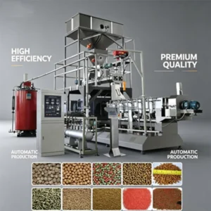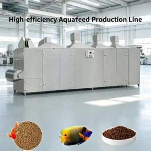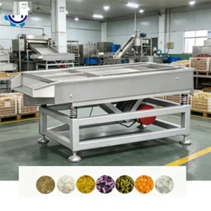
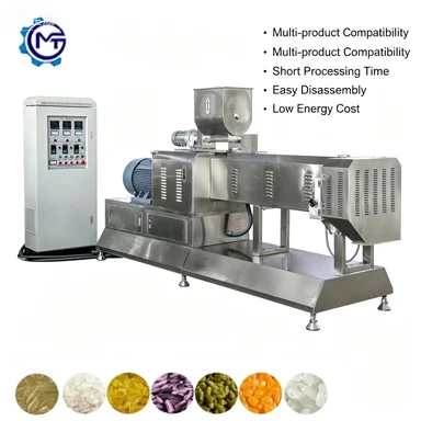
Integrated Line Match — Every station from feeding through pelletizing is calculated for balanced throughput, preventing the common scenario where one machine chokes the rest of the layout.
Technical Specifications
| Parameter | Value |
|---|---|
| Product Type | Aquatic Fish Feed Production Line |
| Screw Configuration | Twin Screw |
| Construction Material | Stainless Steel (main parts) |
| Operation Mode | Fully Automatic |
| Production Type | Continuous |
| Output Capacity | 500 kg/h (basis not stated in source — confirm raw material / moisture / pellet size) |
| Pellet Size Range | 0.5 mm – 12 mm |
| Control System | Simple control panel |
| Line Stations | Feeding, Mixing, Extruding, Pelletizing |
| Certifications | CE, ISO |
Application Suitability
| Application | Material or Output |
|---|---|
| Floating pellet production for carnivorous species | Fish meal, corn gluten, wheat flour blends |
| Sinking pellet production for bottom feeders | High-starch formulations, shrimp feed bases |
| Fry and juvenile feed runs | Micro-pellets down to 0.5 mm diameter |
| Grow-out stage feed runs | Standard pellets up to 12 mm diameter |
What "500 kg/h" Leaves Out About Aquatic Feed Lines
Nominal capacity means nothing when the dryer cannot keep up with the extruder.
Most buyers focus on the extruder output number, but aquatic feed production equipment manufacturer specifications rarely show what happens downstream. When the extruder pushes wet pellets faster than the dryer can handle, moisture sits in the product, causing pellet deformation and mold growth before the product ever reaches the coating drum. [NEED_CITE: moisture content thresholds for safe aquatic feed storage] A balanced line calculation across every station is the only way to verify what a setup actually produces on a buyer’s specific formulation.
Station-by-Station Throughput Alignment
The feeding, mixing, extruding, and pelletizing stations in this aquatic feed line are specified together rather than sourced from separate vendors. Each station’s throughput is matched so the extruder does not starve the mixer or overwhelm the pelletizer. This matching prevents the bottleneck pattern where one oversized machine forces the rest of the layout to run at partial load.
Raw Material Behaviour Across the Line
Aquatic feed formulations vary widely between floating and sinking pellet targets, and each formulation behaves differently through the extruder barrel. High-protein fish meal blends require different screw configuration and barrel temperature profiles than high-starch sinking feed bases. The aquatic fish feed production equipment manufacturer approach here is to confirm screw and die configuration against the buyer’s actual raw material before the line is finalized. [NEED_CITE: twin screw extrusion behaviour with varying protein and starch ratios]
Reading the Specs That Actually Matter
The twin screw configuration handles a broader range of aquatic feed formulations than single screw designs, particularly when formulations include high fat or high moisture content. The 0.5 mm to 12 mm pellet size range covers fry feed through grow-out stages, but the die plate and cutter assembly must be specified for the target diameter at the point of order. Stainless steel construction on the main contact parts addresses the corrosion environment created by fish meal proteins and salt-containing formulations. The simple control panel manages barrel zone temperatures and screw speed, though buyers requiring data logging or remote monitoring should confirm whether PLC or MCC control is available for their installation.
The Cost of Mismatched Station Capacity
When a buyer purchases the extruder alone and adds a dryer or cooler from a different source, the throughput numbers rarely align. Wet pellets accumulate on the conveyor, cooling air distribution becomes uneven, and the final moisture content drifts outside the safe storage range. The result is product loss at the packing stage and customer complaints about pellet durability in the water column. [NEED_CITE: pellet durability standards for aquaculture feed] These mismatches typically surface only after the line is installed and running, when swapping equipment means weeks of downtime.
Why Source the Full Line Together
Every station in this layout — feeding system, mixer, twin screw extruder, pelletizer — is designed and built under one supplier, so throughput calculations hold across the entire sequence. Screw and die configuration is specified to the buyer’s raw material and target pellet density rather than copied from a generic build. An in-house testing workshop runs trial production on the buyer’s actual formulation before shipment, generating a trial run report that confirms product quality and line output. Electrical schematics, voltage, and frequency are confirmed against the destination market before production starts, preventing commissioning delays. Wear parts lists with screw segments and die plates ship with the line so the first replacement cycle does not halt production.
Documentation & Verification
- Line layout drawing showing station-by-station throughput calculation for your pellet size
- Screw and die configuration record matched to your floating or sinking feed formulation
- Trial run report on your raw material produced in the testing workshop before dispatch
- Electrical schematic with confirmed voltage, frequency, and control panel language
- CE declaration of conformity and ISO certificate for customs and local compliance
- Operation manual with barrel temperature profiles for your specific formulation
Installation, Commissioning & Support
- Foundation plan showing footprint and load points for the full feeding-to-pelletizing sequence
- Power supply specification listing dedicated circuit requirements for the extruder main drive
- Assembly sequence for the twin screw barrel sections and die plate on-site
- First-run parameter setting for barrel zones, screw speed, and moisture addition rates
- Operator training covering die changes across the 0.5 mm to 12 mm pellet range
- Wear parts inventory with lead times for replacement screw segments and die plates
Before You Request a Quote
Send the target pellet type — floating or sinking — along with the primary raw materials in your formulation and the desired pellet diameter range. Include your workshop floor dimensions and ceiling height so the line layout accounts for dryer and cooler placement. Specify the local voltage, frequency, and preferred control panel language to avoid rewiring or reprogramming after delivery.
Frequently Asked Questions
Q: How is the 500 kg/h output capacity verified, and what raw material and pellet size is it based on?
A: The capacity figure is a reference point and must be recalculated against your specific formulation, target moisture content, and pellet diameter. We run a trial in the testing workshop using your raw material to confirm actual throughput before the line ships, and the trial report documents the verified output.
Q: How do you configure the screw and die to produce both floating and sinking feed on the same line?
A: Floating and sinking pellets require different screw element arrangements, barrel temperature profiles, and die designs. We specify the screw configuration and die plate to match your primary product target, and changeover procedures are documented in the operation manual if you plan to produce both types.
Q: What voltage, frequency and control language options are confirmed before shipment?
A: We confirm your facility’s voltage and frequency before production, and the electrical schematic is built to match. The control panel language is specified at the order stage so operators can read the interface without translation during commissioning.
Q: Can I run a trial with my own raw material before the line ships, and what does the trial report cover?
A: The in-house testing workshop runs your formulation through the extruder and supporting stations before dispatch. The trial report covers pellet appearance, density, moisture content, and throughput rate, giving you verified data rather than nominal estimates.