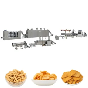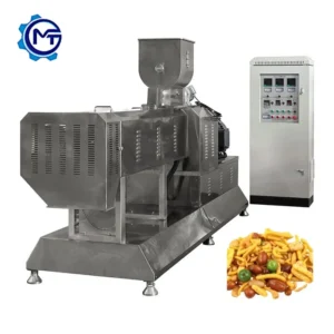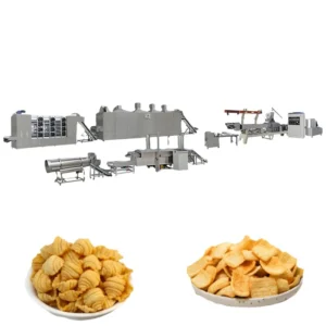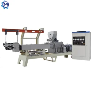
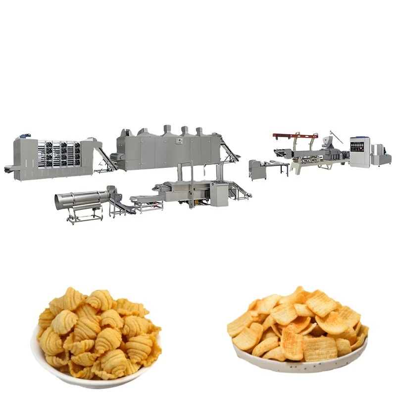
Complete Line Matching — Every station from the mixer through the extruder, cutter, dryer, and fryer is sized to the same throughput, so a fried snacks making machine full equipment range avoids the bottleneck that happens when stations are sourced from separate vendors.
Technical Specifications
| Parameter | Value |
|---|---|
| Model | MT-65 / MT-70 / MT-85 / MT-75 / MT-95 |
| Product Type | Automatic Fried Crispy Bugles Snacks Food Making Machine |
| Screw Type | Twin screw, co-rotating sectional modules |
| Main Motor (MT-65) | 100 kW |
| Main Motor (MT-70) | 130 kW |
| Main Motor (MT-85) | 180 kW |
| Main Motor (MT-75) | 185 kW |
| Main Motor (MT-95) | 280 kW |
| Output Capacity (MT-65) | 120–150 kg/h (basis to be confirmed) |
| Output Capacity (MT-70) | 200–250 kg/h (basis to be confirmed) |
| Output Capacity (MT-85) | 300–500 kg/h (basis to be confirmed) |
| Output Capacity (MT-75) | 400–500 kg/h (basis to be confirmed) |
| Output Capacity (MT-95) | 800–1000 kg/h (basis to be confirmed) |
| Overall Dimensions (MT-65) | 22000 × 1200 × 2200 mm |
| Overall Dimensions (MT-70) | 24000 × 1500 × 2200 mm |
| Mixer Power Options | 4 kW / 7.5 kW / 15 kW (matched to line capacity) |
| Cutting Machine Power | 1.47 kW |
| Cutting Machine Dimensions | 2500 × 600 × 1100 mm |
| Fryer Belt Width | 600 mm stainless steel mesh |
| Fryer Control | Automatic temperature and belt-speed adjustment, roller-assisted feeding |
| Drying & Frying Heating Options | Gas / Electric / Diesel / Fuel gas |
| Voltage & Frequency | Configurable (e.g., 3-phase 380 V 50 Hz, 380 V 60 Hz, 415 V 60 Hz, 220 V 60 Hz) |
| Die Options | Interchangeable dies for bugles, sticks, square sheet, rib chips, diamond chips, wavy chips, pillow shapes, shells, screws, tubes |
| Assembly State | Complete production line (Mixer → Extruder → Cutting/Forming → Dryer → Fryer → Flavouring/Packing) |
| Warranty | 1-year complete warranty, lifetime maintenance service |
| Standards | CE, ISO |
Application Suitability
| Application | Material or Output |
|---|---|
| Bugles and corn horn snacks | Corn powder, wheat flour, potato starch with vegetable oil frying |
| Pillow-shaped and rib chips | Wheat flour and corn starch blends, fried to target crispness |
| Diamond and wavy chips | Potato powder and corn grits formulations |
| Shell, screw, and tube snacks | Corn starch and wheat flour with die-and-roller changes |
| Multi-format fried pellet lines | Single extrusion platform producing several shapes across shifts |
What "Rated Capacity" Leaves Out on Fried Snack Lines
A quoted output number means nothing unless the dryer and fryer can actually keep pace with the extruder on your specific formulation.
I have watched customers assemble a fried snacks making machine full equipment range from two or three different suppliers, only to discover during commissioning that the extruder pushes product faster than the fryer can handle it. The result is a pile of cut pieces waiting on conveyor belts, losing moisture and cracking before they ever reach the oil. [NEED_CITE: production line throughput balancing principles for extruded snack equipment] When the raw material changes — say from standard wheat flour to a high-gluten blend — the extruder may need an entirely different screw combination to maintain the same expansion profile, and the dryer residence time must be recalculated accordingly. Those conversations rarely happen when stations are bought separately.
How Screw Modules Shape the Final Chip
The twin-screw extruder in this line uses co-rotating sectional modules, meaning the screw profile is assembled from individual elements rather than machined as a single shaft. Forward-transport, kneading, reverse-transport, and de-gassing segments are arranged in a sequence matched to the buyer’s flour or starch blend. This is what controls how completely the starch gelatinises inside the barrel and how much expansion occurs at the die face — both of which determine whether the fried chip comes out airy and crisp or dense and hard.
Die and Roller Changes Across Snack Formats
The cutting and forming station sits directly downstream of the extruder and uses an interchangeable die-and-roller system. Swapping from bugles to diamond chips does not require a new extruder barrel; the die plate and forming roller are exchanged, and the cutting speed is adjusted to match the new shape’s geometry. For a fried snacks making machine full equipment range intended to run multiple formats across different shifts, this changeover flexibility determines how many SKUs a single line can realistically support. [NEED_CITE: die and roller changeover procedures for twin-screw extruded snack lines]
What the Motor, Belt, and Heating Specs Actually Mean
The main motor rating across the MT-65 through MT-95 series spans from 100 kW to 280 kW, which directly reflects the shear energy available inside the barrel for cooking and expanding the dough. A higher motor rating allows longer screw assemblies with more kneading zones, giving the operator finer control over product density. The 600 mm stainless steel fryer belt with automatic speed control matters because fryer residence time must match piece thickness; a thicker bugle horn needs a slower belt and slightly lower oil temperature than a thin wavy chip. Heating options across the dryer and fryer — gas, electric, diesel, or fuel gas — let buyers align the line with whatever utility is cheapest or most reliable at the installation site. The configurable voltage and frequency (3-phase 380 V 50 Hz through 415 V 60 Hz) prevent the commissioning delays that occur when a control panel arrives wired for a grid the factory does not have.
The Hidden Cost of Mismatched Stations
When the dryer is undersized relative to the extruder output, cut pieces enter the fryer with too much residual moisture. The oil temperature drops as water flashes off, the chips absorb excess oil, and the finished product has a greasy mouthfeel that the market rejects. I have seen this exact failure on lines where the extruder was upgraded but the dryer was kept from the previous setup. [NEED_CITE: moisture content targets for extruded snack pieces before frying] The waste accumulates quietly — off-spec product gets reprocessed or discarded, and the line never reaches the throughput the buyer planned around.
Why Sourcing the Full Range from One Supplier Matters
Each station in this fried snacks making machine full equipment range is selected so that the extruder output, dryer residence time, and fryer belt capacity align to a single throughput target. Screw configuration and die design are specified to the buyer’s actual raw material rather than copied from a generic template. Before shipment, every line goes through a trial run in the in-house testing workshop using the customer’s own flour, starch, or powder blend — so expansion, density, and frying behaviour are confirmed before the machines leave the factory. Voltage, frequency, and control language are verified against the destination country’s electrical standard before the panel is wired. And the documentation package — layout drawing, capacity calculation, screw record, and trial report — travels with the shipment, giving the installation team a clear reference the day the crates arrive.
Documentation & Verification
- Line layout and capacity calculation showing throughput matching across mixer, extruder, dryer, and fryer
- Screw and die configuration record matched to your corn flour or wheat starch formulation
- Electrical schematic with voltage and frequency confirmed for your site’s power supply
- Trial run report on your actual raw material conducted before dispatch
- CE declaration of conformity and ISO certificate included in the shipment package
- Wear parts list with part numbers for screws, dies, and cutting rollers
Installation, Commissioning & Support
- Foundation and floor-space plan based on the selected model’s overall dimensions (up to 24000 mm line length for MT-70)
- Dedicated electrical circuit sized to the main motor rating (100 kW to 280 kW depending on model)
- Assembly from sectional modules with on-site alignment of extruder barrel, cutter, and fryer belt
- First-run parameter setting including barrel temperature profile and fryer belt speed for your specific chip shape
- Operator training covering die-and-roller changeover between bugles, wavy chips, and pillow shapes
- Recommended two-to-three-year spare parts package covering screws, dies, and cutting roller segments
What to Include in Your Inquiry
Provide the raw material type and formulation you intend to run — corn powder, wheat flour, potato starch, or a blend — along with the target product shapes from the die options list. Specify your local voltage, frequency, and preferred heating source for the dryer and fryer. If you already have upstream mixing or downstream packing equipment, note the interface requirements so the line layout can be matched accordingly.
Frequently Asked Questions
Q: How do I choose the right extruder model based on my target output and raw material?
A: Model selection depends on both the hourly throughput you need and the specific flour or starch blend you plan to extrude. Higher motor ratings allow more kneading zones for denser formulations. We confirm the right model by running your actual raw material in the testing workshop and measuring expansion and density before finalising the quotation.
Q: What supporting stations are available and how are they sized to match the extruder?
A: The line includes a mixer, cutting and forming machine, dryer, fryer, and flavouring station. Each is sized so that its maximum throughput aligns with the extruder model you select. The dryer residence time and fryer belt speed are calculated based on the piece geometry and target moisture content after drying.
Q: Can the die and cutting roller be changed to produce multiple snack shapes on the same line?
A: Yes. The cutting station uses interchangeable dies and forming rollers. Shapes available include bugles, sticks, diamond chips, wavy chips, pillow shapes, shells, screws, and tubes. Changeover involves swapping the die plate and roller and adjusting cutting speed to the new geometry.
Q: What voltage and frequency options are available, and how is control language confirmed?
A: Voltage and frequency are configurable to match your site — common options include 3-phase 380 V 50 Hz, 380 V 60 Hz, and 415 V 60 Hz. The control panel language is confirmed during the specification stage before the electrical cabinet is wired, preventing delays during on-site commissioning.
Q: What wearing parts are included, and what spare parts coverage is recommended?
A: Free wearing parts are included with the initial shipment. We recommend ordering an additional two-to-three-year supply of screws, dies, and cutting roller segments at the time of purchase so that replacements are on hand when the first changeover is due.