
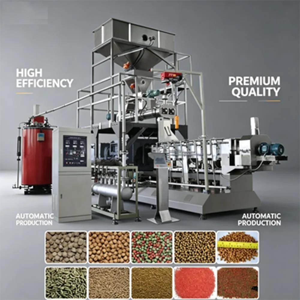
Integrated Station Sizing — throughput calculations across feeding, mixing, extrusion and pelletizing prevent bottlenecking when scaling aquatic feed output.
Technical Specifications
| Parameter | Value |
|---|---|
| Product Type | Twin Screw Floating Fish Feed Extruder Production Line |
| Output Capacity | 500 kg/h (basis not stated in source — confirm raw material formulation, moisture content, pellet size) |
| Screw Configuration | Twin screw |
| Pellet Diameter Range | 0.5 mm to 12 mm via interchangeable die plates |
| Contact Material | Stainless steel on product contact surfaces |
| Control Architecture | Simple control panel (PLC / MCC available on request) |
| Automation Level | Fully automatic, continuous operation |
| Integrated Stations | Feeding, mixing, extruding, pelletizing |
| Power / Voltage / Frequency | To be confirmed based on destination market |
| Dimensions / Weight | To be confirmed based on final line configuration |
Application Suitability
| Application | Material or Output |
|---|---|
| Floating feed for tilapia and catfish | Fish meal, soybean meal, corn flour, wheat middlings, vitamin premix |
| Sinking pellets for bottom-feeding species | Higher-density formulations with adjusted starch-to-protein ratios |
| Larval and juvenile aquatic feed | Fine-diameter pellets (0.5–2.0 mm) from micronized raw materials |
| Shrimp feed and crustacean nutrition | Slow-sinking or water-stable formulations requiring extended barrel residence |
Why "Rated Capacity" Means Nothing Without Your Formula
A twin screw floating fish feed extruder production line for sale at 500 kg/h only holds that number on the exact recipe used to rate it.
I have watched feed producers sign for a line based on a vendor’s test with standard corn starch, then struggle to reach half that output when their actual formula carries 35% fish meal and high fat content. The raw material changes how the screws convey, how the barrel builds pressure, and whether the die produces uniform pellets or misshapen clumps. [NEED_CITE: impact of raw material protein and fat content on extruder throughput and pellet quality] When you review a capacity quote, always ask what recipe, moisture level and pellet size were running during the test — and insist on a trial run with your own formulation before the crate closes.
How Each Station Links to the Next
Buyers surveying full equipment ranges need to see where every machine sits in the flow. The twin screw floating fish feed extruder production line for sale here starts with a volumetric or gravimetric feeder that meters dry ingredients into a ribbon mixer. Mixed powder moves to a preconditioner where steam or water injection begins starch gelatinisation before the twin-screw barrel takes over. The extruder pushes conditioned mash through the die plate, and a cutting mechanism on the die face slices continuous strands into pellet lengths. Each station’s throughput rating must align: if the mixer cycles 600 kg per batch but the extruder consumes 500 kg/h continuously, the buffer bin between them determines whether the line runs without interruption or starves the screws.
Station Sizing Across the Full Equipment Envelope
A common mistake when assembling a catalogue-style line is matching the extruder motor power to the target output while leaving the dryer undersized. Floating pellets leaving the die carry 25–30% moisture and must drop below 10% before bagging; if the dryer cannot remove that water fast enough, the whole line slows to match the dryer’s capacity. The same logic applies downstream to the cooler, the coating drum for fat or palatant application, and the packing scale. [NEED_CITE: typical moisture reduction requirements for floating aquatic feed before storage] Specifying a twin screw floating fish feed extruder production line from a single equipment supplier keeps these throughput calculations under one set of engineering drawings instead of spread across multiple vendor quotes that never cross-reference each other.
Barrel Geometry and Die Selection in Practice
Twin-screw extruders rely on intermeshing screw elements to convey, shear and cook the mash in distinct barrel zones. The L:D ratio — the length of the barrel relative to screw diameter — determines how long the material stays under heat and pressure. A longer barrel gives operators more zones to adjust temperature profile, which matters when switching between high-starch floating pellets and dense sinking formulations. The die plate at the discharge end defines pellet diameter; swapping from a 12 mm die to a 0.5 mm micro-pellet die changes back-pressure inside the barrel, so screw speed and feed rate must be re-tuned accordingly. Stainless steel contact surfaces resist the salt and fat common in fish meal recipes and simplify wash-down between formula changes.
What Happens When Stations Are Spec’d in Isolation
When the extruder is ordered separately from the mixer and dryer, each vendor ships equipment rated on their own test conditions. The result is a line that technically works but cannot reach continuous output without constant operator intervention — the mixer finishes a batch before the extruder is ready, or the dryer backs up because pellets arrive faster than it can handle. [NEED_CITE: consequences of unmatched station capacity in feed extrusion lines] These mismatches rarely surface during the vendor’s factory acceptance test because each machine is demonstrated alone. The cost shows up as lost production hours, inconsistent pellet density and elevated scrap during the first months of operation.
Why This Equipment Range Covers the Gaps
The integrated layout keeps feeding, mixing, extrusion and pelletizing under one equipment package, so throughput at every junction is calculated together rather than guessed. Screw element profiles and die geometry are selected against the buyer’s actual raw material instead of copied from a generic build. An in-house testing workshop allows trial runs on customer-supplied formulations before shipment, catching density or texture issues while adjustments are still inexpensive. Pre-sales engineering includes line layout drawings and utility planning so foundation, power and steam connections are ready when the containers arrive. Documentation — from electrical schematics to trial run reports — travels with the shipment, giving the installation team a single reference instead of conflicting manuals from different vendors.
Documentation & Verification
- Line layout drawing showing station throughput balance for your pellet size range
- Screw and die configuration record matched to your raw material formulation
- Electrical schematic with voltage and frequency tagged for your local grid
- Trial run report using your supplied ingredients, not generic test starch
- Factory acceptance test record with pellet buoyancy and diameter measurements
Installation, Commissioning & Support
- Foundation plan accounts for extruder weight and vibration isolation at full load
- Dedicated electrical circuit sized to main drive motor plus auxiliary heaters
- Stations arrive modular; assembly sequence documented to minimize rigging time
- First-run parameter sheet records barrel zone temperatures and screw RPM for your formula
- Operator training covers die changeover procedure for switching pellet diameters
- Wear parts list identifies screw elements, barrel liners and die plates by part number
What We Need to Configure Your Line
To size the feeding, mixing and extrusion stations correctly, share your target formula including protein, fat and starch percentages, the pellet diameter range you need across growth stages, and your daily production target in finished kilograms. Let us know the voltage and frequency at your facility, the control language your operators prefer, and whether you already have downstream drying or coating equipment the new line must tie into. If you can send a sample of your raw material blend, we run it in the testing workshop and include the results with the proposal.
Frequently Asked Questions
Q: What supporting stations beyond pelletizing are needed to complete a floating fish feed line?
A: After pelletizing, floating feed typically passes through a belt dryer to reduce moisture below 10%, a counterflow cooler to stabilize temperature, a fat or palatant coating drum, and a weighing and bagging station. Each station’s capacity must match the extruder output; otherwise the fastest machine sets the line’s real throughput. We can supply any or all of these stations within the same equipment range.
Q: How is throughput matched between the extruder and upstream mixing or downstream drying?
A: Throughput matching starts with the buyer’s recipe and target pellet size. We calculate the extruder’s continuous consumption rate, then size the mixer’s batch cycle and the dryer’s evaporation capacity to that number with a buffer margin. Buffer bins between stations absorb short interruptions so the extruder never starves and the dryer never floods.
Q: What pellet size range does each die configuration cover, and how are dies swapped?
A: Die plates are available for pellet diameters from 0.5 mm up to 12 mm. Each plate bolts onto the extruder discharge flange; swapping takes one operator with standard hand tools. When changing die diameter, screw speed and feed rate are adjusted to maintain correct back-pressure and pellet density, and the new settings are logged for repeatability.
Q: Can individual stations be ordered separately or only as a complete line?
A: Any station — feeder, mixer, extruder, dryer or packing unit — can be supplied on its own. However, station throughput and control interlocks are calibrated together when ordered as a package. Buyers adding capacity to an existing line usually start with a single extruder and matching dryer, then expand upstream and downstream in later phases.
Q: What is the footprint and utility requirement for the full integrated layout?
A: Footprint depends on extruder capacity, dryer length and the number of buffer bins. Utility needs include three-phase power for all motors, steam or hot water for preconditioning, compressed air for pneumatic gates, and extraction ducting for dust and vapor. We issue a utility matrix with the layout drawing so your contractor can prepare connections before delivery.