Co-rotating screw modules — sectional geometry configured to the buyer’s corn grits particle size and target flake density, not a generic build copied across unrelated cereal lines.
Technical Specifications
| Parameter | Value |
|---|---|
| Product Type | Corn Flakes and Breakfast Cereal Extrusion Processing Line |
| Model | MT-65 / MT-70 / MT-75 / MT-85 |
| Screw Type | Twin-screw, co-rotating, sectional modules |
| Installed Power | 84 kW (MT-65) / 132 kW (MT-70) / 186 kW (MT-75) / 239 kW (MT-85) |
| Real Power Consumption | 59 kW (MT-65) / 92 kW (MT-70) / 140 kW (MT-75) / 167 kW (MT-85) |
| Output Capacity | 120–150 kg/h (MT-65, basis not stated in source) / 200–250 kg/h (MT-70, basis not stated in source) / 300–400 kg/h (MT-75, basis not stated in source) / 400–500 kg/h (MT-85, basis not stated in source) |
| Overall Line Dimensions | 12000×1200×2200 mm (MT-65) / 23000×1500×2200 mm (MT-70) / 24000×1500×2800 mm (MT-75) / 28000×1500×2800 mm (MT-85) |
| Mixer Power / Dimension | 4 kW / 1000×800×1200 mm |
| Screw Conveyor Power / Dimension | 0.75 kW / 2700×500×2400 mm |
| Corn Flakes Press Power | 16.12 kW |
| Corn Flakes Press Dimension | 1550×1300×2000 mm |
| Press Roller Size | 510×310×1050 mm |
| High-Temperature Oven Dimension | 4500×1400×1800 mm |
| Oven Power / Heating Method | 3.75 kW / Gas, both-side baking |
| Sugar Spraying System Power | 28.75 kW |
| Sugar Spraying System Dimension | 4000×1900×1880 mm |
| Sugar Spraying Roller Size | Ø600×2700 mm |
| Control System | Available with PLC or MCC control |
| Gear Box Lubrication | Oil forced automatic lubrication system |
| Cutting System | Non-stop cutting system |
| Extruder Self-Cleaning | Yes |
| Standards | CE |
| Warranty | 1 year complete warranty and life-time maintenance service |
Application Suitability
| Application | Material or Output |
|---|---|
| Corn flakes breakfast cereal | Corn grits, corn flour |
| Multi-grain breakfast cereal | Rice flour, wheat flour, oat flour blends |
| Puffed corn snacks | Corn flour, rice flour |
| Core-filled snacks | Soya bean, peanut, walnut, sugar, chocolate fillings |
| Fortified breakfast cereal | Grain flour with added vitamin and mineral premix |
Why the Mixer-to-Coating Throughput Chain Matters More Than Extruder Output Alone
A corn flakes machine full equipment range is only as productive as its weakest station.
I watched a buyer lose weeks of commissioning time because the flake press downstream of the extruder could not keep up with the pellet feed rate. The extruder was rated for a certain throughput, but the oven and sugar spraying drum created a bottleneck that forced the whole line to run at a fraction of its potential. When you survey a corn flakes machine full equipment range, every station’s capacity must align with the actual raw material behavior, not just a laboratory optimum [NEED_CITE: throughput matching between extrusion and downstream stations].
Station-by-Station Flow from Raw Material to Finished Flake
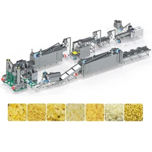
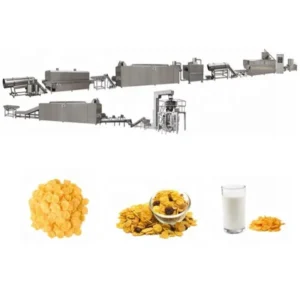
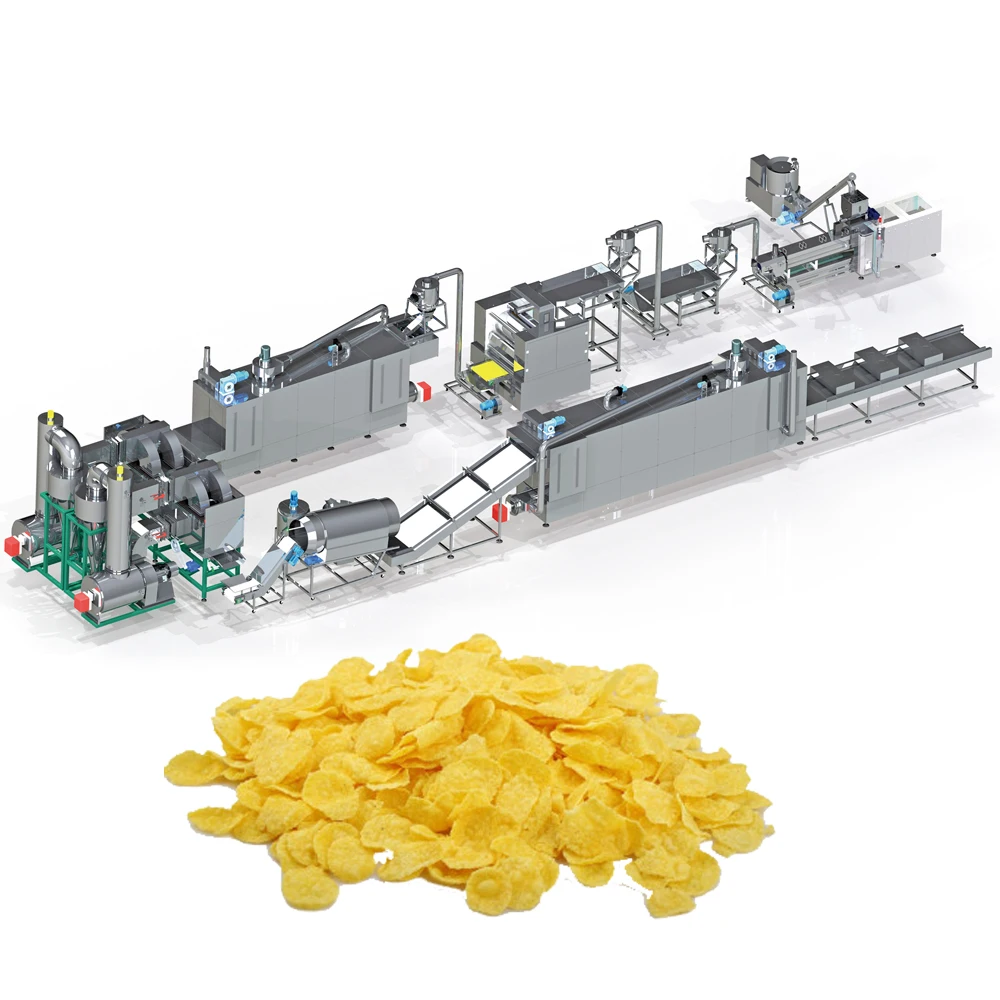
Each unit in this corn flakes machine full equipment range is specified individually so buyers can verify that the mixer batch size, conveyor feed rate, extruder output, press throughput, oven residence time, and coating drum capacity all match the target production volume. The sequence starts with the mixer and screw conveyor feeding corn grits or flour into the twin-screw extruder, where co-rotating sectional screw modules handle forward transport, mixing, cooking, and forming in a single barrel. The extruded pellets then pass through the flake press, where roller distance is adjustable to set flake thickness before the product enters the high-temperature oven.
Coating and Finishing as Part of the Full Range
After baking, the flakes move into the sugar spraying system, where a rotating drum of Ø600×2700 mm applies sweetener or flavoring coating. The total sugar spraying system draws 28.75 kW, which needs to be accounted for in the plant’s utility planning alongside the extruder, press, and oven loads. Buyers surveying the full equipment range should confirm that the coating drum volume matches the oven discharge rate to prevent product buildup or uneven coverage [NEED_CITE: coating drum capacity relative to oven discharge rate in cereal lines].
Reading the Power Draw Across Four Line Sizes
The installed power figures — 84 kW for the MT-65 up to 239 kW for the MT-85 — represent the total connected motor and heating load across every station. The real power consumption values are consistently lower because not every motor runs at full load simultaneously. For plant electrical design, the real power figure is what determines transformer sizing and cable gauge. The difference between installed and real power widens on the larger models, indicating that the MT-75 and MT-85 have greater capacity reserve across the station sequence, which matters when a buyer wants to run heavier dough or higher-moisture recipes that demand more from individual motors.
How Screw Configuration and Oven Method Shape the Final Flake
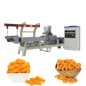
The co-rotating twin-screw design with sectional modules lets the operator rearrange screw elements to change shear profile, residence time, and mixing intensity inside the barrel. A recipe that uses coarse corn grits requires a different screw layout than one based on fine rice flour — the gelatinization temperature and starch damage threshold are not the same. On the thermal side, the gas-fired both-side baking oven ensures that heat reaches the flake from above and below simultaneously, which controls moisture loss rate and final crispness. A single-side heat source tends to curl the flakes and produce uneven color, something that becomes more visible on lighter-colored cereal products where surface consistency matters for retail packaging appearance.
The Hidden Cost of Specifying Stations Separately
When the extruder, flake press, oven, and coating drum are sourced from different vendors, the interface points become the buyer’s problem. A press roller that does not match the extruder’s pellet output rate causes either starvation or flooding. An oven with insufficient belt length for the actual throughput leaves flakes under-baked in the center while the edges scorch. These mismatches surface only during commissioning, when changing a single station means re-negotiating lead times and freight across multiple suppliers [NEED_CITE: interface mismatch risks in multi-vendor food processing lines].
Why Buyers Source the Complete Range from One Builder
Every station in this corn flakes machine full equipment range is specified under one line layout, so throughput calculations across the mixer, extruder, press, oven, and coating drum are verified together before production begins. Screw configuration and die geometry are matched to the buyer’s actual raw material — not a generic default — and confirmed through a trial run in the testing workshop. The gear box oil forced automatic lubrication system and extruder self-cleaning function reduce downtime between product changeovers, which matters for producers running multiple cereal formats on the same platform. Electrical schematics, voltage, frequency, and control language are confirmed before the build starts, so commissioning on site is a matter of connection and calibration rather than troubleshooting fundamental incompatibilities.
Documentation & Verification
- Line layout drawing with throughput matched across mixer, extruder, press, oven, and coating stations
- Machine specification sheet for every station with confirmed voltage and frequency
- Screw and die configuration record matched to the buyer’s corn grits or flour type
- Trial run report on buyer-supplied raw material conducted in the testing workshop before shipment
- Electrical schematic with control language confirmed prior to production
- CE declaration of conformity and factory test record for each line
Installation, Commissioning & Support
- Foundation plan based on the chosen line’s overall dimensions, up to 28000×1500×2800 mm for the MT-85
- Dedicated power circuit sized to real power consumption, up to 167 kW for the MT-85 configuration
- Station-by-station assembly with flake press, oven, and sugar spraying system positioned per the approved layout
- First-run parameter setting including screw speed, barrel temperature profile, press roller gap, and oven gas pressure
- Operator training covering screw module rearrangement, self-cleaning function use, and press roller distance adjustment
- Wear parts list with screws, dies, and press rollers identified for first replacement ordering
Preparing Your Inquiry with the Right Details
To scope the correct line size and station configuration, we need the raw material type and particle size you plan to run, the target daily output based on your shift pattern, and your local voltage and frequency standard. If you are replacing an existing extruder within a running line, share the upstream mixer capacity and downstream oven belt speed so we can match throughput at the interface points. For buyers planning multiple cereal formats from one platform, list every product type and the fillings or coatings involved so the screw configuration and coating drum specification cover the full range from the start.
Frequently Asked Questions
Q: How is output capacity verified per model, and what raw material basis applies?
A: The capacity figures listed for each model — from 120–150 kg/h on the MT-65 to 400–500 kg/h on the MT-85 — are based on specific raw material types and moisture levels that must be confirmed during the pre-sales consultation. We run a trial on the buyer’s actual corn grits or flour in our testing workshop to establish the real throughput before the quotation is finalized.
Q: What is the difference between installed power and real power across the four line sizes?
A: Installed power is the sum of every motor and heater rating across all stations. Real power reflects the actual simultaneous draw during steady production, which is lower because not every component runs at full load at the same time. Real power is the figure used for transformer and cable sizing in your plant electrical design.
Q: Can the flake press roller distance be adjusted for different thicknesses?
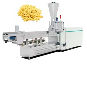
A: Yes. The flake press features an adjustable roller distance that controls flake thickness to meet different market specifications. The big roller design with integrated cooling system maintains consistent flake geometry across long production runs, and the separate controller box allows fine adjustment without stopping the line.
Q: What voltage, frequency, and control language options are confirmed before production?
A: Voltage, frequency, and control language are confirmed during the specification stage before production begins. This covers the PLC or MCC control system, every motor nameplate, and all operator-facing displays. Confirming these details upfront prevents commissioning delays caused by mismatched electrical standards in the buyer’s facility.
Q: Which spare wear parts are included at shipment?
A: Each line ships with a wear parts list identifying screws, dies, and press rollers that will need periodic replacement. The specific spare parts included depend on the line model and the buyer’s production volume, and replacement sourcing is covered under the lifetime maintenance service that accompanies the one-year warranty.