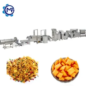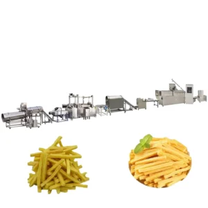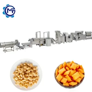
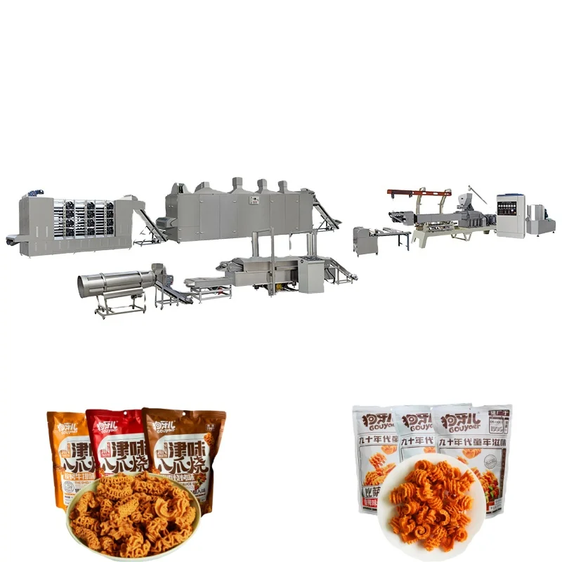
Full-Range Equipment Coverage — every station from mixing through frying is sized and listed here, so throughput balance across the complete fried extruded chips making machine full equipment range can be verified before commitment.
Technical Specifications
| Parameter | Value |
|---|---|
| Model | MT-65 / MT-70 / MT-85 / MT-75 / MT-95 |
| Product Type | Fried Extruded Chips & Pellets Snack Food Production Line |
| Screw Type | Twin-screw, co-rotating, sectional screw modules |
| Main Motor Power | MT-65: 100 kW · MT-70: 130 kW · MT-85: 180 kW · MT-75: 185 kW · MT-95: 280 kW |
| Output Capacity | MT-65: 120–150 kg/h (basis not stated in source); MT-70: 200–250 kg/h (basis not stated); MT-85: 300–500 kg/h (basis not stated); MT-75: 400–500 kg/h (basis not stated); MT-95: 800–1000 kg/h (basis not stated) |
| Mixer Power | 4 kW / 7.5 kW / 15 kW (matched to extruder model) |
| Cutting Machine Power | 1.47 kW |
| Cutting Machine Dimensions | 2500 × 600 × 1100 mm |
| Fryer Belt Width | 600 mm stainless steel |
| Fryer Heating Options | Electricity / fuel gas |
| Drying Method | Gas / Electric / Diesel heating |
| Die Configuration | Interchangeable dies and shaping/cutting rollers |
| Voltage & Frequency | Configurable (e.g. 3ph 380V 50Hz / 3ph 415V 60Hz / 3ph 220V 60Hz) |
| Food-Contact Material | Stainless steel throughout |
| Line Sequence | Mixer → Twin-screw extruder → Cutting/shaping → Fryer |
| Spare Parts | Wearing parts supplied; 2–3 year reserve package recommended |
| Warranty | 1 year complete, lifetime maintenance service |
| Certification | CE, ISO |
Application Suitability
| Application | Material or Output |
|---|---|
| Corn bugles and Fried Flour Corn Bugles | Corn flour blends, with or without legume and whey protein additions |
| Doritos-style triangular chips | Corn flour and wheat flour mixtures |
| Shell, screw and tube-shaped fried snacks | Potato starch, potato powder and corn starch bases |
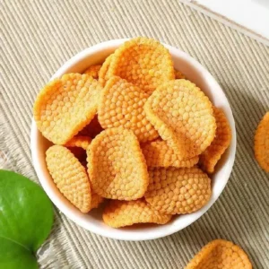
| Wavy and pillow-shaped pellets | Rice flour and blended starch formulations |
| Crisp pea and diamond chip formats | Wheat flour with moisture-controlled blending |
Why Nominal Line Capacity Rarely Survives First Production Week
A fried extruded chips making machine full equipment range quoted on extruder output alone will bottleneck at the fryer or dryer the moment actual raw material hits the line.
I watched a buyer commission a pellet chip line rated for a comfortable mid-range throughput on standard corn flour. Their local formulation included soy flour and whey protein to meet a regional nutrition label, and the extruder output dropped noticeably from the quoted figure. The downstream fryer was now oversized for the slower feed, oil residence time shifted, and surface colour went inconsistent across batches [NEED_CITE: raw material composition effect on extrusion throughput and fryer load balance]. Two weeks of parameter adjustment followed before the line settled. Sizing every station against your actual recipe — not a generic reference material — is the only way throughput figures survive contact with production reality.
Station-by-Station Throughput Matching Across the Fried Extruded Chips Line
Each model in the fried extruded chips making machine full equipment range pairs a specific mixer power rating with its corresponding extruder motor, so blending batch size and extrusion feed rate stay aligned. The cutting machine runs at 1.47 kW across configurations, feeding shaped pieces onto the fryer belt at a rate the 600 mm stainless steel mesh can handle without pile-up or gaps.
When stations are sourced from separate vendors, the extruder vendor quotes one throughput figure and the fryer vendor quotes another — and nobody owns the gap between them. Here the line sequence from mixer through extruder, cutter and fryer is specified as one system, with each motor rating and belt dimension recorded in a single layout document [NEED_CITE: throughput matching methodology for multi-station snack lines].
Die and Roller Geometry for Snack Shape Variety
The interchangeable die and shaping-roller system allows one extrusion platform to produce bugles, square sheet rib chips, diamond chips, wavy chips, pillow shapes, shells, screws, square tubes, round tubes and crisp peas. Switching between shapes means changing the die plate and the corresponding cutting roller rather than replacing the entire forming section.
Different geometries demand different dough expansion behaviour. A bugle shape requires controlled radial expansion with enough structural strength to hold the curved form through the fryer, while a flat diamond chip needs uniform sheet thickness to fry evenly without edge curling. Screw module arrangement inside the barrel and the die land length are both adjusted to match the target shape and the raw material’s gelatinisation characteristics.
Reading the Motor and Fryer Specs Against Your Production Target
The twin-screw co-rotating design with sectional screw modules means the screw configuration can be rebuilt for different raw materials — corn flour, wheat flour, potato starch or rice flour — without replacing the entire screw shaft. Main motor power spans from 100 kW on the MT-65 up to 280 kW on the MT-95, reflecting the increasing barrel volume and the higher torque needed to process denser dough masses at greater throughputs.
The fryer’s 600 mm stainless steel belt and adjustable belt speed let operators control oil residence time independently of the extruder output rate. This matters because a formulation high in potato starch may require a different fry time than a corn-dominant blend to reach the same final moisture and colour [NEED_CITE: fryer belt speed adjustment for starch-variable snack formulations]. Heating options of electricity or fuel gas give flexibility depending on local utility costs and available infrastructure.
The Hidden Cost of Skipping Voltage and Control Confirmation
A fryer rated for one voltage standard shipped to a market running a different frequency will either underheat or trip breakers on the first day. Extruder main motors drawing 100 kW to 280 kW are not forgiving of voltage mismatch — the winding insulation and contactor ratings are specific to the confirmed supply. Control language on the panel must match the operators who will run the line daily, because misread alarms during a fryer temperature excursion can turn a minor fault into extended downtime [NEED_CITE: industrial equipment voltage and frequency standards by export market].
What This Range Delivers Beyond a Machine List
Every station in the fried extruded chips making machine full equipment range is sourced from one supplier, so dimensional compatibility between the extruder discharge and the cutter infeed is confirmed at the design stage rather than discovered during installation.
Screw configuration and die selection are recorded against your specific raw material blend and target product density, not copied from a generic build. The in-house testing workshop runs trial production on your actual formulation before shipment, generating a test report that documents achievable output, product geometry and fry behaviour under real conditions. CE and ISO documentation accompanies each line, and electrical schematics reflect the confirmed voltage and frequency for the destination market.
Documentation & Verification
- Line layout showing throughput calculation for every station from mixer to fryer
- Screw and die configuration record matched to your raw material formulation
- Electrical schematic with confirmed voltage, frequency and control language
- Trial run report on your actual raw material from the in-house testing workshop
- CE declaration of conformity and ISO certificate for the complete line
- Wear parts list with recommended 2–3 year reserve package
Installation, Commissioning & Support
- Foundation plan reflecting the longest line configuration at 24 m length for adequate floor space
- Dedicated power circuit sized for extruder main motor up to 280 kW plus fryer heating load
- Station-by-station assembly sequence from mixer through extruder, cutter and fryer
- First-run parameter setting for screw speed, barrel temperature and fryer belt speed on your material
- Operator training covering die changeover and cutting roller adjustment for shape switching
- Spare screw modules and die plates supplied at shipment per the recommended reserve list
Before You Request a Quote
Share your target product shape and the exact raw material formulation you plan to run, including any legume or protein additions. Confirm your local voltage, frequency and the control language your operators need on the panel. Let us know your available workshop length and ceiling height so the line layout fits your building before production drawings begin.
Frequently Asked Questions
Q: Which stations are included in the standard fried snack line scope?
A: The standard sequence covers the mixer, twin-screw extruder, cutting and shaping machine, and continuous fryer with 600 mm stainless steel belt. Downstream stations such as de-oiling, seasoning, cooling and packing are available and can be added to the layout. Each station’s motor rating and dimensions are documented in the line proposal so you can verify the complete scope against your floor plan.
Q: How do I match mixer, extruder and fryer capacity across the line?
A: Request a line layout with throughput calculation that shows each station’s rated capacity based on your raw material. Mixer batch size must feed the extruder continuously, and the extruder output must match what the fryer belt can process at the required residence time. Sizing from one supplier avoids the gap that opens when stations are quoted independently on different reference materials.
Q: What voltage and frequency configurations are available?
A: The line is configurable for common industrial supplies including 3ph 380V 50Hz, 3ph 415V 60Hz and 3ph 220V 60Hz among others. Voltage, frequency and control panel language are confirmed in writing before production release, and the electrical schematic reflects these values so commissioning proceeds without on-site rewiring or component swaps.
Q: How are die and cutting rollers selected for different chip shapes?
A: Die geometry and cutting roller profiles are chosen based on your target shape — bugles, chips, tubes, shells or waves — and the expansion behaviour of your specific raw material blend. The sectional screw modules are also configured to deliver the dough consistency each shape requires. A trial run on your formulation in the testing workshop confirms the selection before the line ships.