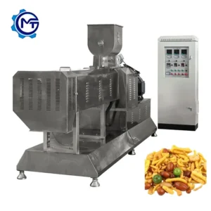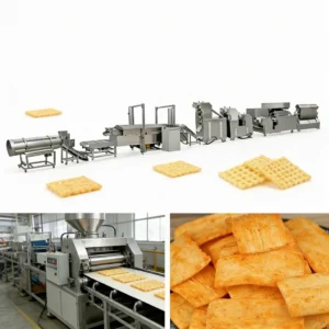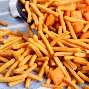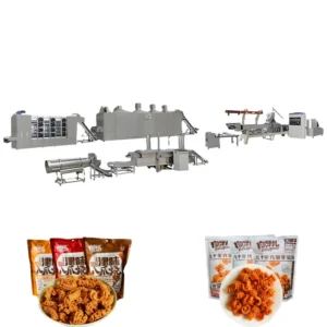
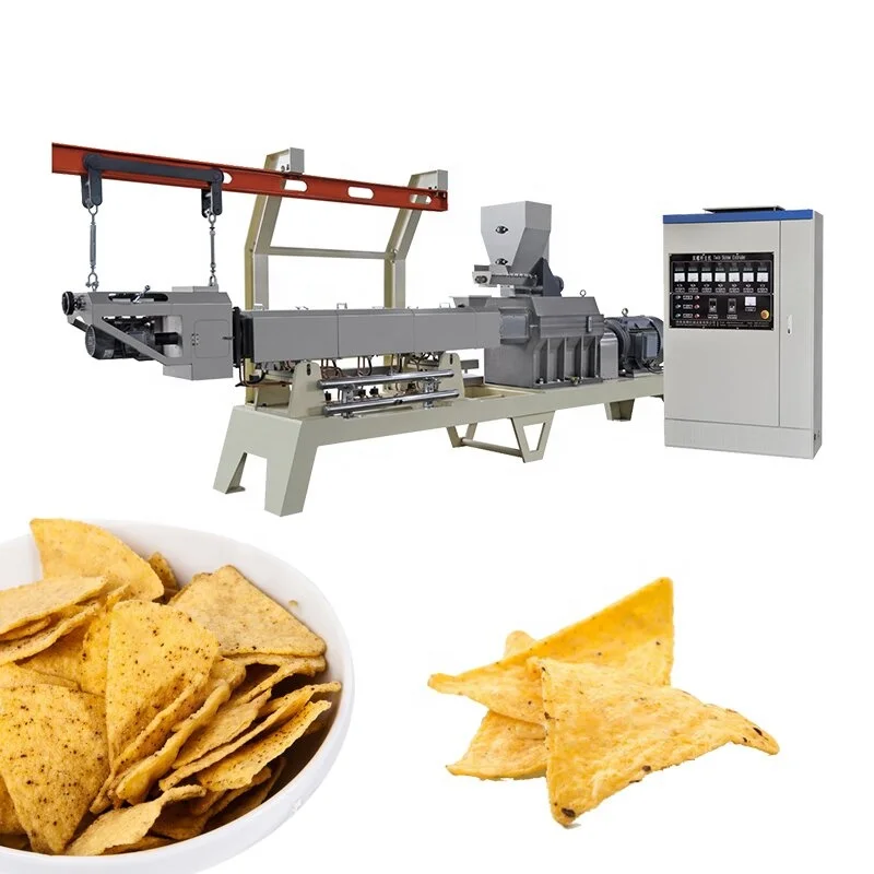
Station-by-station throughput matching — every mixing, extrusion, frying and flavoring unit in this fried chips making machine line is sized so no single stage chokes the others.
Technical Specifications
| Parameter | Value |
|---|---|
| Model | MT100/MT120 |
| Product Type | Fried Potato Chips / Puffed Snack Processing Line |
| Extruder Type | Single Screw Extruder |
| Capacity | 120 kg/h (basis not stated in source — confirm raw material formulation, moisture content and product shape) |
| Rated Power | 50–70 kW (electric heating); 50–60 kW (gas/diesel) |
| Voltage & Frequency | Three-phase 380 V / 50 Hz; single-phase 220 V / 50 Hz (customizable) |
| Overall Dimensions (L × W × H) | 12 000–26 000 × 1 200 × 2 200 mm |
| Construction Material | Food-grade stainless steel 201 (304 available as option) |
| Energy Source Options | Electricity, gas, diesel, steam |
| Motor & Inverter | Siemens (China-made) or top domestic motor; Delixi or Delta inverter |
| Die Configuration | Interchangeable dies — screw shell, round tube, square tube, ring, cartoon shapes |
| Raw Materials | Potato starch, corn starch, wheat flour |
| Standards | CE, ISO 9001 |
| Warranty | One year |
Application Suitability
| Application | Material or Output |
|---|---|
| Secondary-puffed fried pellet chips | Potato starch and corn starch dough extruded into shapes, then fried |
| Golgappa / pani puri shells | Wheat flour and starch blends formed into hollow spheres before frying |
| Shaped snack pellets for seasoning | Ring, tube and cartoon profiles cut from single-screw extrudate |
| Fried screw-shell crisps | Starch-based formulation expanded through die, fried to low-moisture crunch |
What a Capacity Figure Hides When Stations Are Not Balanced
A frying chips making machine full equipment range only delivers its rated output when the fryer belt speed, flavoring drum volume and cooling length are calculated against the extruder’s actual throughput on your formulation.
I once watched a snack line sit idle for an entire afternoon because the fryer belt was specified for a lighter product; by the time the single-screw extruder pushed pellets through at full speed, oil residence time dropped and half the batch came out undercooked. That kind of mismatch never shows up on a spec sheet that lists each station in isolation. Buyers who compare lines on extruder capacity alone often discover the bottleneck only after the first production run [NEED_CITE: line throughput balancing principles in snack extrusion].
Matching the Fryer to the Single-Screw Extruder Output
On this frying chips making machine full equipment range, the automatic fryer follows the pulling-and-cutting station, and its belt length must accommodate the volume of shaped pellets the extruder delivers per minute. If the die produces a dense ring profile, oil contact time needs to be longer than it would for a thin tube shape. That is why we confirm die selection before locking in fryer dimensions, rather than treating the fryer as a fixed accessory.
Flavoring Drum Volume and Cycle Time Alignment
After frying, pellets move to the automatic flavoring line where seasoning powder meets hot product inside a rotating drum. If the drum is undersized relative to the fryer discharge rate, chips pile up and seasoning distribution becomes uneven. We size the drum so that one full rotation coincides with the fryer output pulse, keeping coverage consistent across every batch without manual intervention [NEED_CITE: seasoning adhesion best practices on fried starch snacks].
How Die Geometry Changes Every Downstream Setting
The single-screw extruder ships with interchangeable dies — screw shell, round tube, square tube, ring and cartoon shapes — but switching from a tube to a hollow sphere alters expansion ratio, oil absorption and final bulk density. Each shape therefore demands its own fryer temperature, belt speed and cooling conveyor length. We record the die configuration matched to your target product and use that record to set downstream parameters before the line leaves the factory.
Reading the Power and Voltage Numbers on the Spec Sheet
Rated power spans 50–70 kW under electric heating and 50–60 kW when gas or diesel fires the fryer, which directly affects the transformer capacity you need on site. Three-phase 380 V / 50 Hz is standard, yet many Middle-East and Southeast-Asian facilities run 415 V or 60 Hz; ordering without confirming frequency means motors spin at the wrong RPM and inverters fault on start-up. We treat voltage and frequency confirmation as a gate before production begins, not an afterthought during commissioning.
The Hidden Cost of Skipping a Line-Wide Capacity Check
When the fryer or flavoring drum is sourced separately, the supplier of each station has no incentive to oversize their unit for someone else’s extruder. The result is a line that technically runs but never reaches the throughput you budgeted for, and operators compensate by slowing the extruder — wasting the very capacity you paid for. Those losses compound shift after shift and are rarely traced back to the original specification gap [NEED_CITE: OEE losses from mismatched snack line stations].
Why Sourcing the Complete Equipment Range Here Matters
Every station — mixing system, screw conveyor, single-screw extruder, pulling-and-cutting machine, automatic fryer, flavoring line and cooling conveyor — is configured under one layout drawing, so throughput is verified end-to-end before quotation. Screw and die configurations are recorded against your raw material formulation, not copied from a generic build. The testing workshop runs your actual starch blend before shipment, producing a trial report you can review before the crates are sealed. CE and ISO 9001 documentation ships with every line, and the electrical schematic confirms the exact voltage and control language your operators will see on the HMI. Pre-sales engineering continues through on-site installation, commissioning and operator training so the first production day is never the first time the line runs product.
Documentation & Verification
- Line layout drawing showing station footprints and utility connection points for the full frying chips making machine range
- Machine specification sheet covering motor power, fryer heating method and flavoring drum volume per station
- Screw and die configuration record matched to your starch formulation and target snack shape
- Trial run report on your raw material produced in the testing workshop before dispatch
- Electrical schematic with confirmed voltage, frequency and HMI language
- CE declaration of conformity and ISO 9001 certificate
Installation, Commissioning & Support
- Foundation pad must accommodate up to 26 000 mm line length plus operator walkways on both sides
- Dedicated three-phase 380 V circuit sized for 70 kW peak draw under electric heating configuration
- Stations arrive as individual modules; on-site assembly aligns conveyor transfer heights across extruder, fryer and cooler
- First-run parameter setting covers fryer oil temperature, belt speed and flavoring drum rotation matched to your die shape
- Operator training includes die changeover procedure and fryer mesh-belt tensioning
- Wear-parts list with spare screw, die set and fryer belt section included at shipment
What We Need to Configure Your Line Accurately
Share your target snack format, the exact starch or flour blend you plan to run, and the daily output you need so we can size each station. Confirm your facility voltage, frequency and preferred HMI language to avoid rewiring on arrival. If you already operate upstream mixing or downstream packing equipment, provide interface dimensions so the new line ties in without bottlenecks.
Frequently Asked Questions
Q: How is each station’s capacity matched so the fryer and flavoring line do not bottleneck the extruder?
A: We calculate extruder output on your specific formulation, then size the fryer belt length and flavoring drum volume so each station handles that throughput without product backlog. The line layout drawing shows capacity at every transfer point, and a trial run in our testing workshop verifies actual flow before the line ships.
Q: What die shapes are available, and can custom dies be made for specific snack formats?
A: Standard dies include screw shell, round tube, square tube, ring and cartoon shapes. If your product requires a profile outside this range, we can machine a custom die matched to your target dimensions and expansion ratio, then validate it during the pre-shipment trial run on your raw material.
Q: Which energy source is recommended for the fryer, and how does that affect installed power?
A: Gas or diesel heating keeps electrical demand around 50–60 kW, which suits facilities with limited transformer capacity. Electric heating raises the draw to 50–70 kW but simplifies venting. We confirm your site utility availability before recommending one option and reflect the choice on the electrical schematic.
Q: Can the line be configured with only a subset of stations?
A: Yes. Buyers who already own a mixer or packing system can order the extruder, fryer and flavoring segment alone. We adjust the layout drawing and throughput calculations so the partial line still matches your existing equipment at the infeed and discharge points.
Q: What floor space is needed including operator access and utility clearance?
A: The longest configuration reaches 26 000 mm, and we recommend at least 1 200 mm of walkway on each side plus overhead clearance for fryer exhaust ducting. The line layout drawing provides exact station footprints so your contractor can prepare the foundation and utility stubs before delivery.