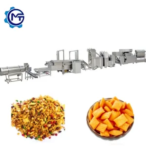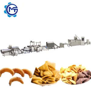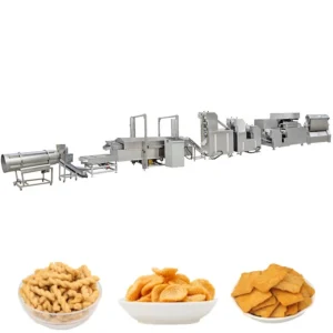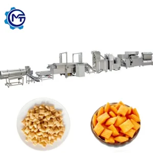
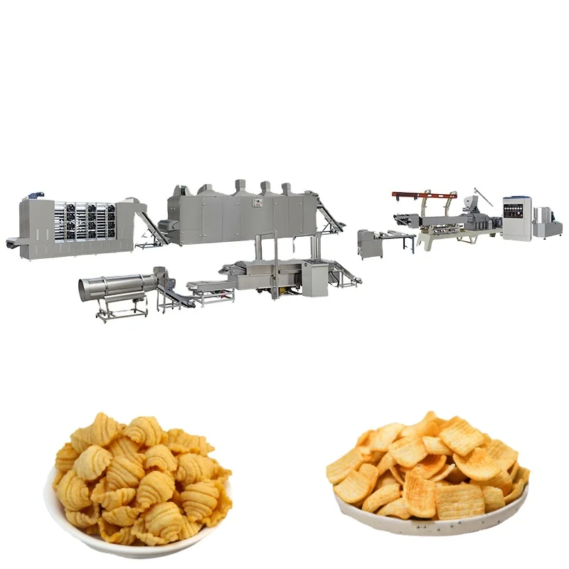
Extrusion and frying stations matched across the line — five twin-screw model tiers from 100 kW to 280 kW paired with a 600 mm belt fryer so throughput at each stage is balanced before the layout is finalised.
Technical Specifications
| Parameter | Value |
|---|---|
| Model | MT-65 / MT-70 / MT-85 / MT-75 / MT-95 |
| Product Type | Automatic Fried Snack Food Production Line |
| Screw Type | Twin screw, co-rotating sectional modules |
| Main Motor | 100 kW (MT-65) / 130 kW (MT-70) / 180 kW (MT-85) / 185 kW (MT-75) / 280 kW (MT-95) |
| Output Capacity | 120–150 kg/h (MT-65) / 200–250 kg/h (MT-70) / 300–500 kg/h (MT-85) / 400–500 kg/h (MT-75) / 800–1000 kg/h (MT-95) (basis not stated in source — confirm raw material formulation and moisture content) |
| Mixer Power | 4 kW / 7.5 kW / 15 kW (matched to line tier) |
| Cutting Machine Power | 1.47 kW |
| Cutting Machine Dimensions | 2500 × 600 × 1100 mm |
| Fryer Belt Width | 600 mm stainless steel mesh belt |
| Fryer Heating | Gas / electric / diesel options |
| Die System | Interchangeable dies for sticks, chips, tubes, bugles, pillow, shell, screw, and specialty shapes |
| Voltage & Frequency | Configurable to buyer supply (e.g., 3ph 380 V 50 Hz / 3ph 415 V 60 Hz / 3ph 220 V 60 Hz) |
| Drying Method | Gas / electric / diesel heating options |
| Line Stations | Mixer → twin-screw extruder → cutting/forming → fryer → flavouring/coating |
| Assembly State | Complete line, turnkey delivery |
| Certification | CE (electronic edition for export; originals viewable at factory) |
| Warranty | 1 year complete line with lifetime maintenance support |
Application Suitability
| Application | Material or Output |
|---|---|
| Bugle and corn chip production | Corn powder, corn starch, wheat flour blends |
| Salad stick and extruded pellet chip lines | Potato starch, potato powder with modified starch |
| Ribbed and wavy fried snack formats | Rice flour and corn grits formulations |
| Shell, screw, and tube-shaped fried snacks | Multi-grain flour mixes with varying moisture |
| Pillow and diamond chip commercial runs | Wheat flour and potato starch composite recipes |
Why the Raw Material Question Must Come Before the Capacity Quote
A frying chips making machine rated on one formulation may not hold that output on your actual recipe.
Buyers often receive a line quoted at a nominal throughput, only to discover during commissioning that their specific starch ratio, moisture level, or protein content changes the expansion behaviour inside the barrel. The extruder runs, but the product density drifts outside what the fryer can handle uniformly. Downstream, the belt fryer receives pieces that absorb oil at different rates, and the final texture misses the market target. This mismatch accounts for a significant share of post-installation re-engineering visits across the snack extrusion sector [NEED_CITE: typical causes of extrusion line commissioning delays].
How Each Station in the Frying Chips Making Machine Range Fits Together
The twin-screw extruder sits at the centre of this frying chips making machine catalogue. Co-rotating sectional screw modules handle forward transport, mixing, de-gassing, cooking, and forming in one continuous pass. Five model tiers — MT-65 through MT-95 — scale from 100 kW to 280 kW, letting buyers match motor rating to the formulation’s shear and thermal demand. The cutting and forming station downstream slices the extrudate to length before it enters the fryer, keeping piece geometry consistent so oil absorption stays uniform across the belt.
Matching Fryer Capacity to Extruder Output
The 600 mm stainless steel belt fryer is sized to receive the full output envelope of the mid-range extruders. Automatic temperature regulation and adjustable belt speed allow operators to dial in residence time for different piece thicknesses. Heating is available in gas, electric, or diesel configurations, selected to match the buyer’s utility cost structure and local fuel availability [NEED_CITE: industrial fryer fuel selection factors for snack food plants]. When throughput is balanced between extruder and fryer, there is no upstream accumulation and no idle belt section wasting thermal energy.
Reading the Spec Sheet Against Your Production Target
Motor power separates the tiers more honestly than a single capacity headline. The MT-65 at 100 kW suits pilot-scale or niche-format runs, while the MT-95 at 280 kW supports high-volume continuous production. Die interchangeability means a single extruder platform can produce sticks, square sheets, rib chips, wavy chips, bugles, and tube shapes without a second machine. Voltage and frequency are configurable — 380 V 50 Hz, 415 V 60 Hz, or 220 V 60 Hz — so the electrical cabinet is wound for the buyer’s actual supply before the machine leaves the factory. Mixer power scales with line capacity, from 4 kW on the smallest tier to 15 kW on the largest, ensuring batch preparation keeps pace with extruder consumption.
What Happens When Stations Are Sourced Separately
A buyer who purchases an extruder from one vendor and a fryer from another often discovers the throughput mismatch only after both machines are bolted to the floor. The extruder may push material faster than the fryer belt can carry it, causing product to pile up at the transfer point and cool below the temperature needed for proper oil entry. Alternatively, an oversized fryer runs half-empty, burning oil faster than product absorbs it and raising free fatty acid levels [NEED_CITE: oil degradation rates in under-loaded continuous fryers]. These problems are invisible in individual machine brochures but show up immediately on a combined line.
Why Procure the Full Equipment Range From One Source
Every station in this frying chips making machine range is specified against the others, so the mixer batch cycle, extruder throughput, cutting speed, fryer belt load, and flavouring drum residence time align before the layout drawing is issued. Screw configuration and die selection are documented against the buyer’s raw material sample, not copied from a generic build. An in-house testing workshop runs trial production on that material before shipment, generating a report that confirms expansion, density, and fry behaviour. Electrical schematics and voltage confirmation are completed during the order stage, avoiding the commissioning delays that arise when a control panel arrives wired for the wrong supply [NEED_CITE: voltage mismatch as a cause of export machinery installation delays]. Wear parts lists — screws, dies, belts — ship with the line so the first replacement cycle does not halt production.
Documentation & Verification
- Line layout drawing showing each station footprint and total space requirement
- Screw and die configuration record matched to your raw material and target shape
- Electrical schematic with voltage and frequency confirmed for your facility
- Trial run report on your actual formulation produced in the testing workshop
- CE declaration of conformity with electronic copy for customs clearance
- Operation and maintenance manual covering every station in the line
Installation, Commissioning & Support
- Floor plan and utility connection points provided before foundation work begins
- Power supply verified against the 100 kW to 280 kW extruder motor range before energisation
- Line arrives in sectional modules for staged assembly within the available hall height
- First-run parameter setting covers barrel temperature zones, screw speed, and fryer belt timing
- Operator training addresses die changeover, fryer temperature adjustment, and safety lockout
- Wear parts inventory includes spare screw elements, dies, and fryer belt sections for the first cycle
Preparing Your Enquiry
Share the raw material formulation you intend to run, including starch type and target moisture content, along with the daily output volume and the product shapes you need from the die set. Confirm your facility’s voltage, phase, and frequency, as well as the control language your operators require. If you have existing upstream mixers or downstream packing equipment, note their throughput so the new line can be matched at the boundaries.
Frequently Asked Questions
Q: How do I choose between the five extruder model tiers for my target output?
A: Start with your raw material formulation and daily production target. Higher starch or protein content demands more shear energy, which shifts the selection toward a larger motor rating even if the nominal kg/h figure seems adequate. The MT-65 suits development runs, while the MT-85 and above support continuous commercial shifts. A trial run on your material confirms the correct tier.
Q: What voltage and frequency options are available for export markets?
A: The control cabinet can be wound for three-phase 380 V 50 Hz, 415 V 60 Hz, 220 V 60 Hz, or other buyer-specified supplies. Voltage and frequency are confirmed during the order stage, and the electrical schematic reflects your local standard before production begins, preventing rewiring delays at commissioning.
Q: How does the die system enable multiple snack shapes on one extruder?
A: Interchangeable dies mount at the extruder outlet, and the cutting roller downstream adjusts to match the new profile. Shape changeover covers sticks, chips, tubes, bugles, shells, and specialty forms. The process requires only a die swap and cutter adjustment, not a replacement extruder or screw rebuild.
Q: How is throughput balanced between the extruder and the fryer?
A: Each line tier is configured so the fryer belt load matches the extruder output envelope. Belt speed and oil temperature are adjustable, and the 600 mm belt width accommodates the full spread of mid-range extruder capacities. This prevents product accumulation at the transfer point and avoids running the fryer under-loaded.
Q: What spare wear parts should I plan for in the first year?
A: Screw elements, die plates, and fryer belt sections experience the most wear. A recommended spare parts list ships with the line, sized for your production hours and material abrasiveness. Ordering the first replacement set at the time of the main equipment purchase avoids lead-time gaps when consumption parts reach their service limit.