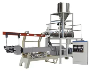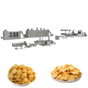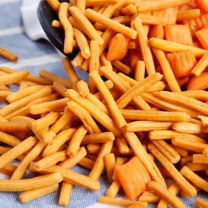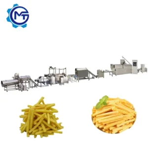
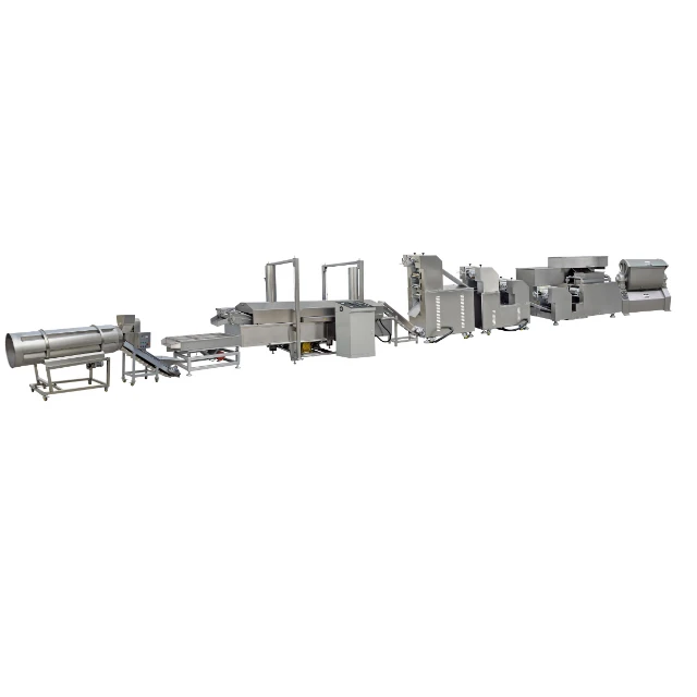
Single-source throughput matching — every station from the mixer through the fryer is sized against your starch formulation and target chip geometry, not assembled from separate catalogues and left to bottleneck at the dryer.
Technical Specifications
| Parameter | Value |
|---|---|
| Product Type | Fried Pellet Chips and Bugles Snack Extrusion Line |
| Extruder Models Available | MT-65 / MT-70 / MT-85 / MT-75 / MT-95 |
| Screw Type | Twin-screw, co-rotating with sectional modules |
| Main Motor (MT-65) | 100 kW |
| Main Motor (MT-70) | 130 kW |
| Main Motor (MT-85) | 180 kW |
| Main Motor (MT-75) | 185 kW |
| Main Motor (MT-95) | 280 kW |
| Output Capacity (MT-65) | 120–150 kg/h (basis not stated in source — confirm raw material, moisture and pellet format) |
| Output Capacity (MT-70) | 200–250 kg/h (basis not stated in source — confirm raw material, moisture and pellet format) |
| Output Capacity (MT-85) | 300–500 kg/h (basis not stated in source — confirm raw material, moisture and pellet format) |
| Output Capacity (MT-75) | 400–500 kg/h (basis not stated in source — confirm raw material, moisture and pellet format) |
| Output Capacity (MT-95) | 800–1000 kg/h (basis not stated in source — confirm raw material, moisture and pellet format) |
| Mixer Power Options | 4 kW / 7.5 kW / 15 kW (matched to extruder model) |
| Cutting Machine Power | 1.47 kW |
| Cutting Machine Dimensions | 2500 × 600 × 1100 mm |
| Fryer Belt Width | 600 mm stainless steel mesh belt |
| Fryer Energy Options | Electricity / fuel gas |
| Drying Method | Gas / electric / diesel heating |
| Voltage & Frequency | Customizable (e.g., 3ph 380V 50Hz, 3ph 415V 60Hz, 3ph 220V 60Hz) |
| Control System | PLC and MCC with configurable interface language |
| Die Configuration | Interchangeable dies for bugles, sticks, square sheet, rib chips, diamond chips, wavy chips, pillow shapes, shell, screw, square tube, round tube, wave |
| Raw Material Contact Parts | Food-grade stainless steel throughout |
| Warranty | 1 year complete with lifetime maintenance service |
| Certifications | CE, ISO |
Application Suitability
| Application | Material or Output |
|---|---|
| Bugles and 3D corn chips | Corn flour, corn starch blends at controlled moisture |
| Fried pellet snack shells and tubes | Wheat flour and potato starch formulations |
| Ribbed and wavy fried chips | Potato powder with corn starch carrier |
| Pillow-shaped fried pellets | Multi-grain starch blends for snack manufacturers |
| Screw and round tube fried snacks | Starch-based dough with adjustable gelatinisation targets |
What "500 kg/h" Actually Means on a Fried Pellet Chips Making Machine Full Equipment Range
Output figures only hold when the raw material, moisture content, and pellet format match the basis used for the calculation.
I have stood in snack plants in the Gulf where the extruder was pushing pellets at full rated speed, but the dryer could not drop moisture fast enough, and half the product went into rework bins before it ever reached the fryer. The quoted capacity looked good on paper. On the floor, the line was effectively running at a fraction of that number because throughput matching across stations was never validated against the buyer’s actual starch formulation. This is one of the most common failures when a fried pellet chips making machine full equipment range is assembled from separate vendors [NEED_CITE: throughput mismatch between extruder and dryer in snack lines].
Every Station Sized to the Same Throughput Target
A fried pellet chips making machine full equipment range only performs when the mixer output, extruder throughput, dryer residence time, and fryer belt speed are calculated together. The line stations here — mixer, twin-screw extruder, cutting and forming machine, dryer, fryer, flavouring drum, cooler, and packing conveyor — are all specified under one supplier so the capacity at each point is balanced against the others. This prevents the situation where one station idles while the next station chokes.
Die and Roller Changeover Without Replacing the Extruder
The cutting and forming station uses interchangeable dies and rollers that allow shape changeover across bugles, shells, tubes, waves, pillows, and flat sheet formats. For a snack manufacturer planning to test multiple chip geometries on a single extrusion platform, this means the product range can expand without adding a second extruder or reconfiguring the upstream mixing and conveying equipment.
How Screw Configuration Shapes the Pellet Before It Reaches the Fryer
Twin-screw extrusion with sectional modules allows the screw profile to be adjusted along the barrel length. The compression ratio and shear intensity at each section control how completely the starch gelatinises, which directly determines the pellet density and, ultimately, how the chip expands when it hits hot oil [NEED_CITE: starch gelatinisation and expansion behaviour in twin-screw extrusion]. A screw combination that works for a corn flour bugle will produce a different texture on a potato starch shell, which is why the screw and die configuration record should always reference the buyer’s specific formulation rather than a generic build sheet. The MT-series extruders span five models with main motors from 100 kW to 280 kW, giving enough range to match motor power and screw speed to the actual dough viscosity and target output tier.
Why the Fryer Belt Width and Energy Source Matter More Than They Look
The 600 mm stainless steel mesh belt in the fryer sets the maximum product load per linear metre of fryer length. If the extruder is producing pellets at a rate that exceeds what the belt can carry in a single layer without overlapping, the chips will fry unevenly — some over-browned, some under-cooked. Belt speed is adjustable, and temperature control is automatic across electricity or fuel gas heating, but the belt width is a hard physical constraint that must be reconciled with the extruder output during line design. Choosing the wrong fryer energy source for a site with limited gas supply or unstable grid capacity can delay commissioning by weeks [NEED_CITE: industrial fryer energy infrastructure requirements in emerging markets].
The Cost of Skipping the Trial Run
I have seen lines shipped to the Middle East where the buyer’s local corn flour had a different particle size distribution than the flour used during factory testing. The pellets came out of the extruder with inconsistent wall thickness, and in the fryer they expanded unevenly — some chips stayed dense while others ballooned and cracked. A trial run on the buyer’s actual raw material in the testing workshop, with a written report covering pellet density, moisture drop across the dryer, and fryer expansion behaviour, catches these mismatches before the machines leave the factory.
Why Buyers Specify This Line Over Assembled Alternatives
The line is supplied as a single package from batching to packing, so throughput calculations are owned by one engineering team rather than split between vendors who each guarantee only their own station. Screw configuration and die design are specified against the buyer’s raw material and target chip shape, not copied from a generic template. The in-house testing workshop allows trial runs on customer-supplied flour and starch before shipment, meaning product development starts weeks earlier. Voltage, frequency, and control interface language are confirmed before production begins, reducing the chance of rewiring delays on site. Pre-sales consultation carries through to on-site installation, commissioning, and operator training with a documented wear parts list for the first replacement cycle.
Documentation & Verification
- Line layout showing throughput matching between extruder, dryer, and fryer for your starch blend
- Screw and die configuration record tied to your raw material formulation and chip shape
- Trial run report on your own flour and starch before dispatch
- Electrical schematic with voltage, frequency, and control language confirmed pre-production
- CE declaration of conformity and ISO certificate in electronic edition for customs clearance
- Wear parts list with recommended spare screws, dies, and fryer belt components
Installation, Commissioning & Support
- Floor plan drafted against your workshop dimensions accounting for the longest extruder footprint at over 24 metres for the MT-70 configuration
- Dedicated electrical circuit sized to the extruder main motor rating up to 280 kW on the MT-95
- Fryer gas line or electrical supply confirmed against local utility capacity before shipment
- PLC and MCC commissioning with control language set to your operator team’s requirement
- Operator training covering screw module changes, die swaps, and fryer belt tension adjustment
- Free wearing parts included at shipment with a two-to-three-year supplementary spare parts list
What to Share When Requesting a Quotation
To configure the fried pellet chips making machine full equipment range accurately, provide your raw material formulation including flour type, starch ratio, and target moisture at the extruder inlet. Specify the chip shapes you plan to produce and the daily output target in finished weight. Share your workshop length, width, and clear height so the line layout can be drafted to fit, and confirm your local voltage, phase, and frequency along with the preferred control interface language.
Frequently Asked Questions
Q: How is each station’s capacity matched, and what is the output figure based on?
A: Every station from mixer to packing is calculated against the same raw material, moisture level, and pellet format. The output figures in the specification sheet are reference ranges for each extruder model. The actual confirmed capacity depends on your specific starch formulation and target chip density, which is validated during the trial run before shipment.
Q: What voltage, frequency, and control language options are confirmed before production?
A: The electrical system is configurable across common industrial standards including 380V 50Hz, 415V 60Hz, and 220V 60Hz three-phase supplies. The PLC and MCC interface language is set to match your operator team. All electrical parameters are documented in the schematic and confirmed in writing before the machines enter production.
Q: Which spare wearing parts are included, and what should I plan for the first two to three years?
A: A set of free wearing parts ships with the line, covering initial screw and die replacements. A supplementary spare parts list covering additional screws, die inserts, and fryer belt components is recommended for the first two to three years of operation to avoid unplanned downtime.
Q: Is a trial run on my raw material conducted before shipment?
A: Yes. Your raw material is run through the extruder and downstream stations in the testing workshop. The trial run report documents pellet density, moisture reduction across the dryer, frying expansion behaviour, and final chip texture so that product development is well advanced before the line arrives at your facility.
Q: Can the line layout be adapted to my existing workshop dimensions?
A: The layout is drafted against your floor plan including length, width, and ceiling height. The longest configurations exceed 24 metres, so adequate straight-line space or an L-shaped arrangement is planned during the proposal stage to ensure every station fits without compromising access for maintenance.