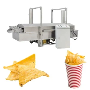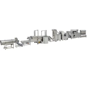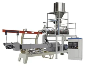
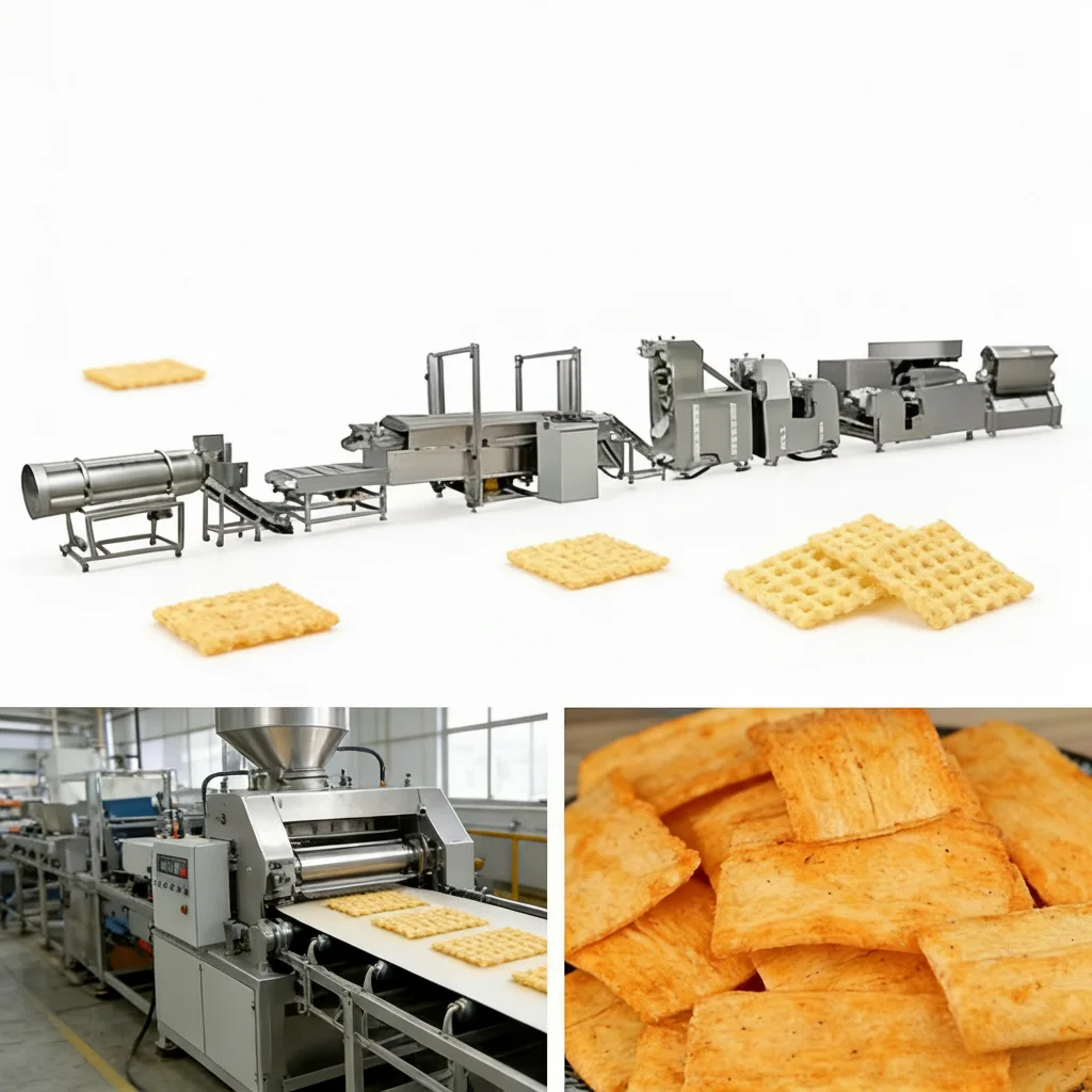
Thermally Balanced Stations — fryer, flavoring drum and cooling conveyor each sized to the extruder’s actual throughput so nothing sits idle or overflows on your real formulation.
Technical Specifications
| Parameter | Value |
|---|---|
| Product Type | Frying Chips Making Machine / Puffed Snack Production Line |
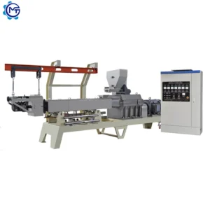
| Screw Type | Single screw extruder |
| Output Capacity | 120 kg/h (basis not stated in source — confirm raw material formulation, moisture content and product shape before quoting) |
| Rated Power | 50–70 kW (electricity); 50–60 kW (gas/diesel) |
| Voltage & Frequency | 380 V / 50 Hz three-phase; 220 V / 50 Hz single-phase; customizable to local voltage |
| Overall Dimensions (L×W×H) | 12,000–26,000 × 1,200 × 2,200 mm |
| Line Stations | Mixer → Screw Conveyor → Single Screw Extruder → Pulling and Cutting Machine → Automatic Fryer → Automatic Flavoring Line → Cooling |
| Raw Materials | Wheat flour, corn starch, potato starch |
| Energy Options | Electricity / gas / diesel / steam |
| Material of Construction | Food-grade stainless steel 201 (304 available per spec table) |
| Electrical Components | Siemens motor (made in China) or China top-brand motor; Delixi or Delta inverter |
| Die Configuration | Adjustable dies for screw shell, round tube, square tube, ring, cartoon shapes |
| Certification | CE / ISO 9001 |
| Warranty | One year |
Application Suitability
| Application | Material or Output |
|---|---|
| Fried pellet chip production | Wheat flour and corn starch blends shaped into tubes, rings, or shells before frying |
| Golgappa / pani puri sheet snacks | Wheat flour and potato starch formulations cut into flat rounds for secondary puffing in hot oil |
| Extruded cartoon-shaped snack chips | Corn starch based doughs formed through adjustable cartoon dies, then fried and seasoned |
| Savory screw shell puffed snacks | Single screw extrusion of starch mixtures into spiral shell profiles for frying and powder coating |
| Fortified snack pellet lines | Blends incorporating nutritional additives processed through the same station flow with die changes |
Why the Fryer Size Matters More Than the Extruder Rating
A frying chips making machine line only runs as fast as its slowest station.
When buyers focus on extruder output and skip the downstream matching, the fryer becomes the bottleneck. I have watched starch chip lines where the extruder pushed product into a fryer that could not keep up, forcing operators to idle the screw conveyor every few minutes just to clear the belt. The result is inconsistent oil absorption, uneven color, and product that does not meet the density the market expects [NEED_CITE: fryer residence time and throughput matching in starch snack lines].
Mapping Every Station Before You Commit
Buyers surveying equipment before specifying a new line need to see every station, not just the extruder brochure. The frying chips making machine full equipment range laid out here covers mixing, screw conveying, single screw extrusion, pulling and cutting, automatic frying, automatic flavoring, and cooling. Each station is selected so its capacity aligns with the others, which means the throughput you see on paper is the throughput you get on the floor.
Matching Oil Temperature to Starch Gelatinization
The single screw extruder partially gelatinizes the starch dough, but the fryer finishes the job. If oil temperature drops because product enters faster than the heating system recovers, the chips absorb excess oil and emerge limp rather than crisp. This is why the fryer on this line is rated for the same throughput band as the extruder, with enough thermal recovery margin to hold temperature across varying product shapes. Whether you run thin round tubes that flash-fry quickly or thick screw shells that need longer residence, the thermal balance stays within the target window [NEED_CITE: oil temperature recovery rates in continuous snack fryers].
What the Die Profile Means for Downstream Handling
Adjustable dies for screw shells, round tubes, square tubes, rings, and cartoon shapes give format flexibility, but each profile behaves differently after the cutter. Flat rounds for golgappa tend to stick together on the conveyor if spacing is too tight, while hollow tubes can trap moisture inside and require a slightly longer fry cycle. The pulling and cutting machine is set up to adjust pull speed and cut length so the product enters the fryer with consistent spacing and geometry, reducing the amount of manual sorting operators need to do at the cooling end.
The Hidden Cost of Undersized Flavoring Drums
A seasoning drum that turns too slowly leaves patches of uncoated product; one that turns too fast breaks fragile fried chips before they reach the packer. On lines where the flavoring drum was spec’d independently of the fryer output, I have seen breakage rates climb noticeably because chips spent too long tumbling against each other. The automatic flavoring line here is matched to the upstream flow rate, with drum speed and powder feed rate calibrated together so each batch exits with even coverage and minimal breakage [NEED_CITE: flavoring drum speed and snack breakage correlation].
Why Procurement Alignment Matters Here
Every station from mixer to cooling conveyor comes from one supplier, so throughput calculations are done against the same product formulation rather than stitched together from separate vendor quotes. The single screw extruder’s screw configuration and die design are specified to your starch blend and target chip shape before production begins. An in-house testing workshop runs your actual raw material through the line before shipment, catching moisture or density mismatches at the factory instead of on your floor. Electrical schematics, voltage confirmation, and control language are locked in during the engineering phase so commissioning does not stall over a wrong frequency or an unlabeled panel. Pre-sales consultation through on-site installation, operator training, and ongoing wear parts support keeps the line running after the first production day.
Documentation & Verification
- Line layout and capacity calculation confirming throughput match from mixer through cooling
- Screw and die configuration record tied to your starch formulation and target chip shape
- Electrical schematic with voltage, frequency, and panel language confirmed for your destination market
- Factory test record from trial run on your actual raw material before dispatch
- CE declaration of conformity and ISO 9001 certificate for customs and regulatory entry
- Wear parts list with screw, die, and cutter blade reorder references
Installation, Commissioning & Support
- Footprint ranges up to 26 meters long — confirm workshop length and column spacing before foundation work
- Power draw up to 70 kW on electricity — dedicated circuit and breaker sizing required at your panel
- Line ships in modular station groups — plan forklift access and overhead clearance for assembly
- First run includes die alignment, fryer temperature ramp, and flavoring drum calibration on your material
- Operator training covers screw speed, oil temperature, pull rate, and seasoning feed adjustments
- Wear parts list provided at commissioning with first replacement intervals for screws, dies, and cutter blades
What to Send With Your Inquiry
Provide your starch formulation details including flour type, starch ratio, and target moisture content so the die and screw configuration can be matched before quoting. Confirm your local voltage, phase, and frequency along with preferred control panel language to avoid delays during commissioning. Share your workshop length and ceiling height so the line layout fits your available space without station crowding.
Frequently Asked Questions
Q: How is the 120 kg/h output capacity verified, and on which raw material formulation and product shape is it based?
A: The stated output of 120 kg/h is recorded without a confirmed raw material formulation, moisture level, or specific die profile in the source data. Before committing to a production target, we run your actual starch blend and chosen chip shape through the testing workshop and document the measured throughput. This ensures the number on your quotation reflects your real conditions, not a generic benchmark.
Q: What voltage, frequency, and control language options are confirmed before shipment?
A: Standard configurations include 380 V / 50 Hz three-phase and 220 V / 50 Hz single-phase, with customization available for local grid conditions. The electrical schematic is reviewed with you during the engineering phase so that frequency, phase, breaker ratings, and control panel language all match your destination market before the line leaves the factory.
Q: How are fryer and flavoring drum capacities matched to the extruder output to avoid line bottlenecks?
A: Each station is sized using the same throughput calculation based on your formulation and product shape. The fryer’s thermal recovery rate and belt speed are set so product residence time stays consistent, while the flavoring drum’s rotation speed and powder feed rate are calibrated to the same flow rate. This prevents upstream product from piling up or downstream stations from running idle.
Q: Which die configurations are available, and how are they selected for different chip shapes and densities?
A: Adjustable dies cover screw shells, round tubes, square tubes, rings, and custom cartoon shapes. Selection depends on your target market format and the density the end consumer expects. During the trial run we test your chosen die with your starch formulation to verify expansion, wall thickness, and frying behavior, adjusting screw configuration if the texture falls outside specification.
Q: What energy source options are supported at each station, and how does that affect installed power?
A: Electricity, gas, diesel, and steam are available as energy options across the line. Choosing gas or diesel for the fryer can reduce the electrical load on your panel, while electric heating offers more precise temperature control. The rated power range shifts depending on which energy source you select at each station, and this is reflected in the final electrical schematic.