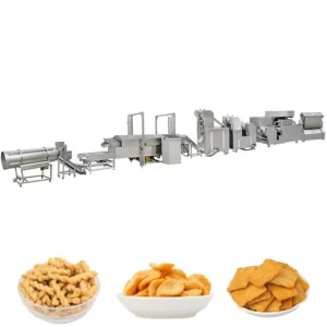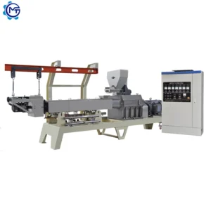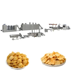
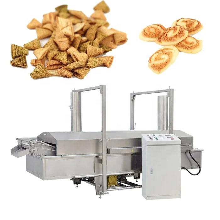
Throughput-Matched Stations — every mixer, extruder, fryer and flavoring drum in this fried snack line is specified as one balanced system rather than sourced from separate vendors and forced together on the factory floor.
Technical Specifications
| Parameter | Value |
|---|---|
| Model | MT65 / MT70 / MT85 / MT75 / MT95 |
| Product Type | Fried Bugles Snack Production Line |
| Extruder Type | Double Screw Extruder |
| Installed Power | 142 kW (MT65), 185 kW (MT70), 240 kW (MT85), 245 kW (MT75), 370 kW (MT95) |
| Actual Running Power | 100 kW (MT65), 130 kW (MT70), 180 kW (MT85), 185 kW (MT75), 280 kW (MT95) |
| Output Capacity | 120–150 kg/h (MT65, basis to be confirmed), 200–250 kg/h (MT70, basis to be confirmed), 300–500 kg/h (MT85, basis to be confirmed), 400–500 kg/h (MT75, basis to be confirmed), 800–1000 kg/h (MT95, basis to be confirmed) |
| Overall Line Dimensions | 22000×1200×2200 mm (MT65) to 30000×1500×2800 mm (MT95) |
| Powder Mixer Tank Volume | 150 kg |
| Powder Mixer Rotary Speed | 385 rpm |
| Powder Mixer Power | 4 kW |
| Fryer Temperature Range | 0–260 °C |
| Fryer Dimensions | 4500×1350×2350 mm |
| Flavor Line Output | 400 kg/h |
| Flavor Line Power | 1.5 kW |
| Contact Material | Food-grade stainless steel |
| Assembly State | Complete line: mixing → extrusion → frying → flavoring |
| Warranty | 1 year complete warranty |
| Certification | CE |
Application Suitability
| Application | Material or Output |
|---|---|
| Fried bugles and wonderful crisp corners | Wheat flour, corn flour, starch-based blends |
| Tortilla-style triangular chips | Corn masa and wheat flour formulations |
| Small fish crisps and golden corners | Rice flour and composite grain blends |
| Shaped snacks (ducks, gourds, Christmas trees) | Flour-based doughs with adjustable moisture |
| Small to mid-scale retail snack production | Continuous output across five capacity tiers |
What "Nominal Line Capacity" Really Means on a Frying Chips Making Machine
A capacity figure only holds if every station upstream and downstream can sustain it on your actual flour formulation.
I once spent three days on a site in Colombia rebalancing a continuous fryer line because the extruder was pushing product faster than the de-oiling section could handle. Oil temperature dropped, half the batch came out soggy, and the nominal capacity was never reached in steady state. When evaluating a frying chips making machine, the number on the brochure matters far less than whether the mixer, extruder, fryer belt length, and flavoring drum are genuinely rated to the same throughput on the material you plan to run [NEED_CITE: continuous fryer throughput balancing principles]. Each MT65 through MT95 configuration lists capacity at the line level, but the raw material basis for each figure should be confirmed against your specific flour blend before the order is locked in.
How Station Matching Prevents Fryer Bottlenecks
A fryer does not run alone. The frying chips making machine full equipment range shown here pairs a double screw extruder with a continuous fryer rated to 0–260 °C, which covers the typical window needed for flour-based puffed products. If the extruder output exceeds what the fryer belt can carry at the correct residence time, product piles up at the fryer infeed, moisture content drops unevenly, and the final texture shifts batch by batch. Matching these two stations on paper before fabrication removes the most common cause of on-site rework.
Why Flour Formulation Dictates Screw and Die Selection
Different flour blends behave very differently inside a twin-screw barrel. A high-gluten wheat flour requires a different screw pitch and moisture profile than a corn-dominant blend, and the die geometry determines whether the extrudate holds the bugle shape through frying or collapses. The extruder on this line allows screw configuration and die design to be set based on your raw material sample, and trial runs can be conducted in the testing workshop before the line ships [NEED_CITE: twin-screw extrusion die design for shaped snacks]. This step prevents the situation where the machine arrives, the die is wrong for the flour, and product development starts from scratch on the buyer’s floor.
Reading the Power and Dimension Figures
The gap between installed power and actual running power is worth noting — on the MT65, installed capacity is 142 kW while typical draw sits around 100 kW. This difference reflects motor starting loads and heater reserve rather than continuous consumption, and it matters when sizing the workshop’s electrical supply. The powder mixer at 4 kW and 385 rpm is matched to a 150 kg tank volume, meaning batch mixing time is roughly 10 minutes, which needs to align with the extruder’s consumption rate to avoid idle periods. The fryer dimensions of 4500×1350×2350 mm determine belt length and therefore residence time at a given belt speed — a longer belt allows slower frying at lower oil temperatures, which is gentler on delicate shapes like small gourds and Christmas trees. Line footprint stretches from 22 metres for the MT65 up to 30 metres for the MT95, so workshop length and ceiling height must be confirmed early.
The Cost of Ignoring Downstream Capacity
When the flavoring drum cannot keep pace with the fryer output, product accumulates in cooling conveyors and absorbs ambient moisture before seasoning. The result is uneven coating adhesion and a shelf life that falls short of market expectations. I have seen producers blame the fryer for a problem that was entirely downstream [NEED_CITE: seasoning adhesion issues on continuous snack lines]. On this line, the flavor station is rated at 400 kg/h, which needs to be verified against the actual extruder output for your chosen model and flour blend to confirm there is no accumulation point between frying and packing.
Why Procurement Here Differs from Assembling Individual Machines
Every station from the 150 kg powder mixer through the double screw extruder to the continuous fryer and flavoring drum comes from a single equipment source, which means throughput calculations are cross-checked internally rather than left to the buyer to reconcile. Screw and die configuration is set against your raw material, not copied from a generic build. Voltage, frequency and control language are confirmed before fabrication, reducing commissioning delays at your facility. An in-house testing workshop allows trial runs on your flour blend so that product shape, expansion and frying behaviour are validated before the frying chips making machine leaves the factory. Pre-sales engineering covers line layout, utility planning and throughput matching as one package rather than separate conversations with multiple vendors [NEED_CITE: turnkey food processing line project coordination].
Documentation & Verification
- Line layout drawing showing matched throughput at mixer, extruder, fryer and flavoring stations
- Screw and die configuration record tailored to your flour formulation and target snack shape
- Electrical schematic with voltage and frequency confirmation for your destination market
- Trial run report on your raw material conducted in the testing workshop before dispatch
- CE declaration of conformity covering the complete line assembly
- Operation and maintenance manual with wear parts list for screws, dies and fryer belt
Installation, Commissioning & Support
- Workshop length must accommodate 22 to 30 metres of line footprint depending on model selected
- Electrical supply should be sized for the actual running power of your chosen model with dedicated breaker circuits
- Line arrives in modular sections requiring on-site assembly, belt alignment and utility connection
- First commissioning run includes screw speed, barrel temperature and fryer belt speed calibration to your flour blend
- Operator training covers mixer batch timing, extruder feed rate and fryer temperature management
- Wear parts list identifies screws, dies and fryer belt sections for first reorder planning
- Ongoing maintenance support addresses throughput rebalancing if raw material formulation changes
Preparing Your Inquiry
To move from a general frying chips making machine inquiry to a firm line configuration, share the flour formulation you plan to run, the target snack shape and size, your required hourly output, and the electrical standards at your facility. Include workshop dimensions and ceiling height so the layout can be drafted accurately. If you have existing upstream or downstream equipment that this line must integrate with, provide those specifications as well.
Frequently Asked Questions
Q: How is output capacity verified for each station on this fried snack line?
A: Each station — mixer, extruder, fryer and flavor drum — has its own rated throughput. These figures are cross-checked during line configuration to confirm no single machine creates a bottleneck. The raw material basis for each capacity claim should be confirmed against your flour formulation before the order is finalized, and a trial run in the testing workshop validates the numbers on your actual material.
Q: What voltage and frequency options are available for different export markets?
A: Voltage and frequency are confirmed during the specification stage before production begins. The electrical schematic is prepared to match your facility’s supply, and control panel labeling and language are set accordingly. Providing your local electrical standards early in the inquiry prevents commissioning delays on site.
Q: Can the screw and die be customized for my specific flour blend and snack shape?
A: Yes. Screw pitch, element arrangement and die geometry are selected based on your raw material sample and the target product shape — whether bugles, triangles, fish crisps or other forms. A trial run on your flour blend is conducted in the testing workshop before shipment to confirm expansion, shape retention and frying behavior.
Q: How do you prevent bottlenecks between the extruder, fryer and flavor line?
A: Throughput at each station is calculated together during line design rather than specified independently. The fryer belt length and speed are matched to extruder output, and the flavoring drum capacity is verified against fryer discharge rate. This cross-station matching is reviewed in the line layout proposal before fabrication starts.
Q: What spare wear parts come with the initial shipment?
A: A wear parts list is provided with every line quotation, typically covering screws, die plates and fryer belt sections most likely to need replacement during the first production year. Confirming this list before shipment ensures you have replacements on hand when the first changeover is due.