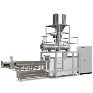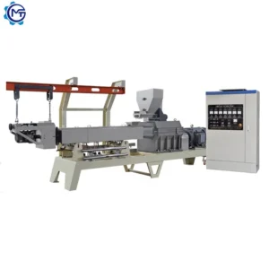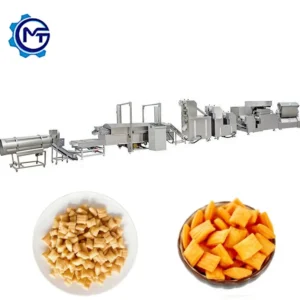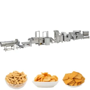
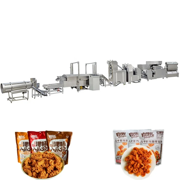
Integrated line design — every station from mixer to cooling conveyor is sized against the same throughput target so the extruder never starves the fryer or overloads the flavoring drum.
Technical Specifications
| Parameter | Value |
|---|---|
| Product Type | Puffed Snack Processing Line with Single Screw Extruder and Fryer |
| Extruder Type | Single Screw Extruder |
| Screw Configuration | High and low pressure screw |
| Output Capacity | 120 kg/h (basis not stated in source — confirm raw material formulation and moisture content) |
| Rated Power | 50–70 kW |
| Electric Heating Power | Approx. 100 kW (source value — verify against manufacturer catalog) |
| Gas / Diesel Heating Power | 50–60 kW (source value — verify against manufacturer catalog) |
| Voltage & Frequency | Three-phase 380V/50Hz; single-phase 220V/50Hz (customizable) |
| Energy Options | Electricity, gas, diesel, steam |
| Motor & Inverter | Siemens (China-made) or top Chinese brand motor; Delixi or Delta inverter |
| Overall Dimensions (L×W×H) | 12,000–26,000 × 1,200 × 2,200 mm |
| Construction Material | Food-grade stainless steel 201 / 304 |
| Die Configuration | Interchangeable dies for screw shell, round tube, square tube, ring, cartoon shapes |
| Process Flow | Mixer → Screw Conveyor → Single Screw Extruder → Pulling and Cutting Machine → Automatic Fryer → Automatic Flavoring Line → Cooling |
| Certification | CE, ISO 9001 |
Application Suitability
| Application | Material or Output |
|---|---|
| Secondary puffing snack production | Wheat flour, corn starch, potato starch blends for golgappa and pani puri |
| Octopus-shaped puffed snacks | Starch-based formulations extruded into hollow forms then fried |
| Pellet-derived snack shapes | Screw shells, tubes, rings, and cartoon shapes from single screw extrusion |
| Fried chip and crisp formats | Pre-extruded pellets expanded in hot oil for uniform blister and crunch |
Why the Fryer Capacity Question Matters More Than Extruder Output
A 120 kg/h extruder feeding a fryer rated for 80 kg/h means product piles up, oil temperature drops, and half your batch exits undercooked.
When buyers focus on the extruder number alone, the downstream stations quietly become the real constraint. The pulling and cutting machine has to keep pace with whatever the screw pushes out, and the automatic fryer needs enough residence time and oil volume to finish each piece at the right moisture level. I once watched a Southeast Asian snack producer lose an entire shift because the flavoring drum was undersized — product cooled below coating temperature before it even reached the drum, and seasoning adhesion fell apart. Matching throughput across every station is the difference between a line that runs and a line that constantly needs operator intervention. [NEED_CITE: thermal load calculation for continuous industrial fryers in snack production]
Every Station in the Puffed Snack Processing Line Full Equipment Range
The line begins with a mixer that conditions wheat flour, corn starch, or potato starch to a consistent moisture level before a screw conveyor meters it into the single screw extruder. Inside the barrel, the high-and-low-pressure screw configuration generates the shear and temperature profile needed to gelatinise starch without requiring a twin-screw setup. The extrudate exits through an interchangeable die, and a pulling and cutting machine sections it into uniform lengths before the pieces enter the automatic fryer. This sequence defines what a complete puffed snack processing line full equipment range should cover — no orphan stations, no capacity gaps between extrusion and frying.
How the Fryer, Flavoring Drum, and Cooling Conveyor Close the Loop
After frying, the hot product moves directly into the automatic flavoring drum where powdered or oil-based seasoning is applied while surface oil is still tacky enough to hold the coating. Timing here is critical: if the cooling conveyor pulls product away too fast, seasoning falls off; too slow, and pieces clump together before packing. The multi-energy fryer design — available with electricity, gas, diesel, or steam heating — lets producers match the thermal station to local utility costs and availability rather than forcing a single fuel type. [NEED_CITE: energy source selection for industrial frying systems in emerging markets] This flexibility is especially relevant for buyers operating in regions where gas is cheaper but electrical infrastructure is more reliable.
Reading the Screw, Die, and Power Specs Against Your Target Product
The single screw extruder uses a high-and-low-pressure screw configuration that creates distinct compression zones along the barrel, allowing it to handle starch-heavy formulations that would stall a conventional single-pitch screw. Interchangeable dies let one extruder produce screw shells, round tubes, square tubes, rings, and cartoon shapes — changing the die is a mechanical swap, not a full reconfiguration. Rated power sits at 50–70 kW for the extruder alone, which is typical for this output class when running dense starch blends. The overall line footprint spans 12 to 26 metres in length, so workshop planning must account for the full run including the fryer, flavoring station, and cooling section. Electrical supply must be confirmed at three-phase 380V/50Hz or the local equivalent before the control panels are wired.
What Happens When Stations Are Specified in Isolation
An extruder running at full output into an undersized fryer causes oil temperature to collapse every few minutes, producing pale, oily snacks that fail texture tests. I have seen this exact bottleneck force operators to deliberately slow the extruder, which then creates surging in the screw conveyor and uneven feed density. The flavoring drum compounds the problem if its rotation speed and baffle design do not match the product flow rate — you end up with over-seasoned clusters and under-seasoned singles in the same batch. These mismatches rarely appear in a quotation that lists machines individually; they only surface during commissioning when the whole line runs together for the first time. [NEED_CITE: throughput balancing methodology for multi-station snack processing lines]
What Makes This Line Build Different
Complete station coverage from batching through cooling means one supplier is responsible for throughput matching across every junction, eliminating finger-pointing between separate equipment vendors. The screw configuration and die design are specified against the buyer’s actual raw material formulation rather than copied from a generic build, which matters when a customer switches from standard wheat flour to a high-amylose starch blend. An in-house testing workshop allows trial runs on the buyer’s own ingredients before the line ships — I have used this to catch expansion failures that would otherwise surface only after installation. Pre-sales consultation covers line layout, utility planning, and electrical confirmation so that voltage and control language match the destination factory before production begins.
Documentation & Verification
- Line layout drawing showing every station position and material flow direction for the puffed snack line
- Machine specification sheets for extruder, fryer, and flavoring drum with matched throughput figures
- Screw and die configuration record tied to your raw material formulation
- Electrical schematic with voltage and frequency confirmed for your local supply standard
- Trial run report produced on your supplied ingredients before shipment
- CE declaration of conformity and ISO 9001 certificate for the complete line
Installation, Commissioning & Support
- Foundation must support the 12–26 m line footprint with level flooring across extruder and fryer stations
- Dedicated three-phase circuit required for the 50–70 kW extruder motor plus fryer heating load
- Extruder barrel and screw arrive assembled; fryer tank ships drained and is filled on site
- First-run commissioning includes die selection, screw speed tuning, and fryer temperature profiling
- Operator training covers die changeover, fryer oil management, and flavoring drum adjustment
- Wear parts list covers screws, dies, fryer mesh belts, and flavoring drum seals
Before You Send the Inquiry
Share your raw material formulation — especially the starch type and target moisture content — along with the product shapes you intend to run, so the screw configuration and die set can be matched from the start. Confirm your workshop length and ceiling height against the 12–26 metre line footprint, and specify local voltage and frequency to avoid rewiring delays during commissioning. If you have existing upstream mixers or downstream packing equipment, note their throughput so the new stations can be balanced to the same rate.
Frequently Asked Questions
Q: What stations are included in the full line and where does each one fit in the process flow?
A: The line covers mixer, screw conveyor, single screw extruder, pulling and cutting machine, automatic fryer, automatic flavoring line, and cooling conveyor in that sequence. Each station is sized so that product flows continuously without accumulating between stages. The layout drawing provided with the quotation maps every station position and material transfer point.
Q: How is throughput matched between the extruder, fryer, and flavoring stations?
A: Each station’s capacity is calculated against the extruder output so the fryer has adequate oil volume and residence time, and the flavoring drum rotation speed matches the product feed rate. This prevents bottlenecks where one machine forces the others to run below their rated speed.
Q: Which energy sources are available for the fryer, and how do I choose?
A: The fryer supports electricity, gas, diesel, or steam heating. Choice depends on local fuel cost, supply reliability, and factory infrastructure. Gas heating typically offers lower running cost where piped gas is available, while electric heating simplifies installation in facilities without gas lines.
Q: What shapes can be produced, and how are dies changed between runs?
A: Interchangeable dies produce screw shells, round tubes, square tubes, rings, and cartoon shapes from the same extruder. Die changeover is a mechanical swap at the extruder barrel head — the pulling and cutting machine settings are then adjusted to match the new profile length.